Battery Not Charging from Solar: Step-by-Step Diagnostic Guide
Key takeaway: When your batteries aren’t charging from solar, work through the problem systematically from the panels down to the battery. Nine times out of ten, the issue is something simple: wrong time of day, a tripped breaker, incorrect charge controller settings, or a BMS lockout. Grab a multimeter and follow this guide from Step 1. I’ve diagnosed dozens of “dead” solar systems, and only twice was the problem actually a failed component.
What You’ll Need
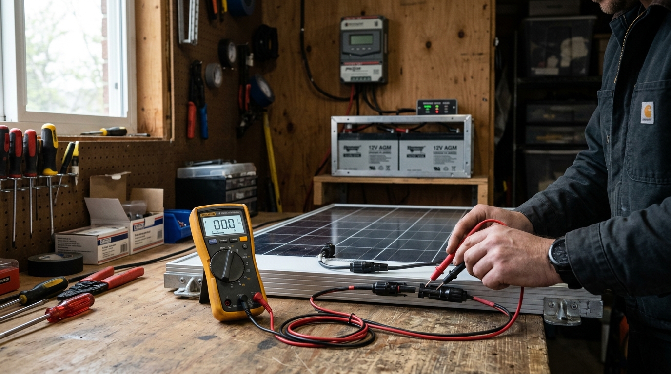
- A digital multimeter (any basic model works — a $20 unit from the hardware store is fine)
- Access to your charge controller display or monitoring app
- The spec sheet for your solar panels (specifically the Voc and Isc ratings)
- Access to your battery bank and BMS (if separate)
- 10-15 minutes of patience
If you don’t own a multimeter yet, stop and buy one. It is the single most useful tool for solar troubleshooting. You cannot diagnose charging problems by staring at components.
Step 1: Is There Actually Sunlight?
This sounds obvious, but mismatched expectations cause more “my system is broken” moments than actual failures.
What to Check
- Time of day. If it’s before 9 AM or after 4 PM, your panels may only produce 20-40% of their rated power. At dawn and dusk, they produce almost nothing.
- Weather. Thick overcast cuts production by 60-80%. Light clouds cut 20-40%. Rain or heavy fog can reduce output to near zero.
- Shading. Walk outside and look at your panels. Is anything casting a shadow? Even partial shade on one panel in a series string can collapse the output of the entire string. A single shadow across a few cells can cut production by 50% or more.
- Season. If you installed in June and it’s now December, you may be getting half the sun hours you’re used to. Winter days are shorter and the sun angle is lower.
What’s Normal
On a clear day at solar noon, expect 75-85% of your panels’ rated output. A 400W panel realistically produces 300-340W in ideal conditions. If your panels are producing in that range and the battery still isn’t charging, move to Step 2.
For a full breakdown of why panels underperform and how to diagnose shading and other output issues, see the solar panels low output troubleshooting guide.
Step 2: Check Panel Voltage with a Multimeter
This is where real diagnostics begin. You need to know if your panels are actually generating power.
How to Measure
- Set your multimeter to DC voltage (the V with a straight line, not the wavy line).
- Measure voltage at the panel’s MC4 connectors or at the junction box. If you can’t access the panels directly, measure at the charge controller’s PV input terminals.
- Compare the reading to your panel’s Voc (open-circuit voltage) from the spec sheet.
What the Numbers Mean
Example: You have 4 x 400W panels wired in series. Each panel has a Voc of 49.5V. In series, expected Voc = 4 × 49.5V = 198V.
| Your Reading | What It Means |
|---|---|
| 180-198V | Normal. Panels are working. Under load (charging), voltage drops to Vmp range — this is expected. |
| 130-175V | Low. Likely partial shading, one panel underperforming, or a bad connection in the string. |
| 40-50V | Only one panel is contributing. You have a broken connection, blown fuse, or disconnected MC4 somewhere in the string. |
| 0V | No power from panels. Check MC4 connections, fuses, breakers, and DC disconnect switches between panels and charge controller. |
| Negative voltage | Your positive and negative leads are swapped at some point in the wiring. This won’t charge — it can damage equipment. Fix immediately. |
If panel voltage looks normal but the battery still isn’t charging, the problem is downstream. Move to Step 3.
If panel voltage is zero or very low, the problem is in the array or the wiring between panels and charge controller. Skip to Step 6 (wiring checks).
Step 3: Check the Charge Controller Display
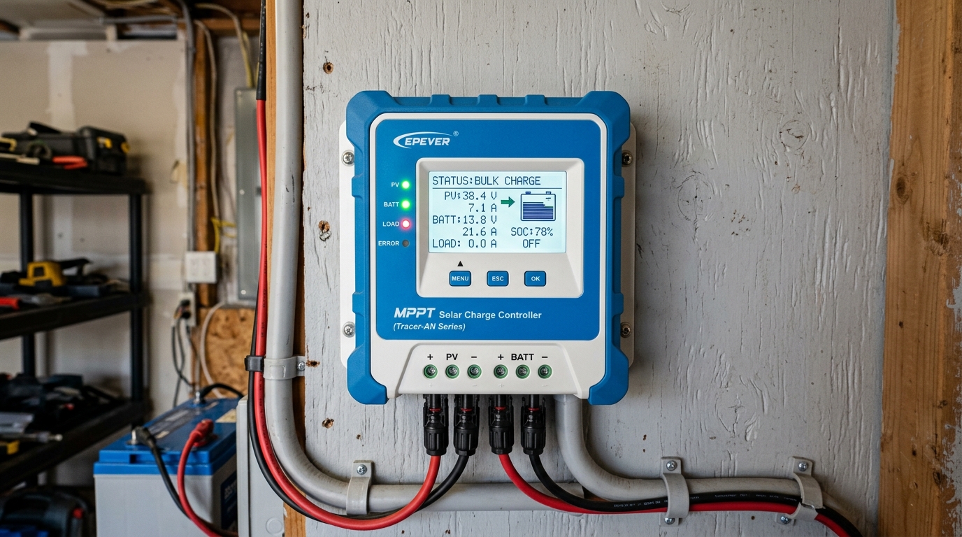
The charge controller is the brain of your charging system. Its display (or app, for Bluetooth-equipped models) tells you what it thinks is happening.
What to Look For
- PV input voltage: Does it match what you measured in Step 2? If the controller shows 0V but you measured 180V at the PV terminals, you may have a wiring issue between the terminals and the controller’s internal circuit, or the controller itself has failed.
- PV input current: Is it showing any amps? If voltage is present but current is 0A, the controller isn’t pulling power from the panels. This could be because the battery is full, the controller is in a fault state, or the settings are wrong.
- Charging state: What mode is the controller in? Common states:
- Bulk: Actively charging. Maximum current flowing. This is normal.
- Absorption: Battery is nearly full. Controller holds voltage steady while current tapers. Normal.
- Float: Battery is full. Controller provides minimal maintenance current. This is not a problem — your battery is charged.
- Off/Standby: Controller is not charging. This is the problem state — investigate why.
- Fault/Error: The controller detected a problem. Check the error code against the manufacturer’s documentation. If you’re running an EG4 or Growatt inverter with a built-in charge controller, see the inverter error codes guide for specific code lookups.
- Battery voltage: What does the controller think the battery voltage is?
The “Float Trap”
I get messages about this constantly. Someone installs a system, watches it charge all day the first day, and then the next morning panics because the charge controller shows “Float” and only 0.2A going to the batteries.
This is normal. If your batteries charged fully yesterday and you didn’t use much power overnight, they’re still nearly full in the morning. The controller enters float mode quickly because the batteries don’t need much energy. As you use power during the day, the controller will shift back to bulk charging.
Check your battery’s state of charge (SOC). If it’s above 90%, the controller is doing its job. There’s no problem to fix.
Step 4: Check Battery Voltage — Is It Already Full?
Measure the battery voltage directly at the battery terminals with your multimeter.
Voltage Reference for Common Battery Types
| Battery Type | Nominal | ”Full” (resting) | “Empty” | Charging Absorb | Float |
|---|---|---|---|---|---|
| 12V LiFePO4 | 12.8V | 13.4-13.6V | 12.0V | 14.2-14.6V | 13.4-13.6V |
| 24V LiFePO4 | 25.6V | 26.8-27.2V | 24.0V | 28.4-29.2V | 26.8-27.2V |
| 48V LiFePO4 | 51.2V | 53.6-54.4V | 48.0V | 56.0-57.6V | 53.6-54.4V |
| 12V Lead-Acid (FLA) | 12.0V | 12.7-12.8V | 11.8V | 14.4-14.8V | 13.2-13.4V |
| 12V AGM | 12.0V | 12.8-12.9V | 11.8V | 14.4-14.6V | 13.4-13.6V |
If the battery voltage is in the “full” range, your battery is charged. The charge controller is correctly not pushing more power in. There’s no fault — you just have a fully charged battery.
If the battery voltage is low but the charge controller shows no current flowing, the problem is between the charge controller and the battery (settings, wiring, or BMS). Move to Step 5.
If the battery voltage doesn’t match what the charge controller displays, you have a wiring or connection problem between them. Skip to Step 6.
Step 5: Charge Controller Settings — Correct Battery Type and Voltage?
Wrong settings are the second most common cause of charging failures, right after “it’s cloudy.” Someone buys LiFePO4 batteries but leaves the charge controller on its default lead-acid profile — it happens constantly.
What to Verify
- Battery type setting: Is it set to LiFePO4 (sometimes called “lithium,” “LFP,” or “User Defined”)? If it’s set to lead-acid, the charge voltages will be wrong for lithium batteries, and vice versa. Lead-acid absorb voltage (14.4V for 12V) is too low for many LiFePO4 configurations, so the controller may stop charging before the battery is actually full.
- Absorb voltage: Must match your battery manufacturer’s specification. For 48V LiFePO4, this is typically 56.0-57.6V. Too low means the battery never fully charges. Too high risks triggering the BMS over-voltage cutoff.
- Float voltage: Typically 2-4V below absorb for 48V systems. Again, match your battery spec.
- Max charge current: Some controllers default to a low current limit. If you have a 100A charge controller but it’s set to limit output to 20A, charging will be much slower than expected.
- Low-temperature cutoff (if available): Some MPPT controllers can disable charging below a set temperature to protect LiFePO4 cells. If this is enabled and your batteries are cold, charging stops intentionally.
How to Fix
- Look up your battery manufacturer’s recommended charge parameters. They’re in the manual or on the manufacturer’s website.
- Enter those exact values into the charge controller. Don’t guess, don’t round, don’t “close enough” it.
- If your charge controller supports CAN bus or RS485 communication with your battery, use it. The battery will tell the controller exactly what voltage and current it wants. This eliminates settings errors entirely.
I’ve built battery banks from raw cells — the process of configuring a BMS and setting charge parameters is detailed in the DIY LiFePO4 battery bank guide. Even if you bought pre-built batteries, that guide explains the charging parameters and why they matter.
Step 6: Wiring — Connections, Fuses, and Breakers
If you’ve confirmed panels produce voltage, the charge controller sees it, settings are correct, and the battery isn’t full — you have a wiring issue.
MC4 Connections (Solar Panel Side)
MC4 connectors are supposed to be weatherproof, but they fail more often than people expect.
- Check every MC4 pair. Pull them apart, inspect for moisture, corrosion, or melted plastic. Reconnect firmly until you hear the click.
- Check polarity. A reversed MC4 connection in a parallel string will create a short circuit through the panels. This is a common wiring mistake — positive of one string connected to negative of another.
- Check junction boxes on the back of panels. On cheaper panels, the solder joints inside can crack from thermal cycling. If a panel’s voltage reads 0V individually, the junction box is the most likely failure point.
Fuses and Breakers
This one gets people all the time. There’s a blown fuse or tripped breaker somewhere in the circuit that nobody remembers installing.
- Check every fuse and breaker between panels and charge controller, and between charge controller and battery.
- DC disconnect switches — are they in the ON position? I’ve spent 45 minutes troubleshooting a system only to find the DC disconnect switch between the panels and the charge controller was off. The homeowner’s kid had flipped it while playing in the garage.
- Inline fuses on battery cables. Many LiFePO4 batteries ship with an inline fuse holder on the positive cable. Check it. Some fuse holders also have poor contact quality — the fuse looks fine but the holder’s spring contacts are corroded or loose.
- Combiner box fuses if you’re running multiple panel strings. A blown fuse in one string won’t produce an obvious error — the other strings may still charge, just at reduced power.
Wire Gauge and Voltage Drop
If everything is connected and nothing is blown, but charging current is much lower than expected, voltage drop in the wiring may be the problem.
I measured this on a friend’s system last year. He had 20 feet of 10 AWG wire running from his panels to the charge controller. At 30A, he was losing 3.2V across that run. On a 48V system, that’s a 6.7% loss — the charge controller was receiving less power than the panels were producing, and the efficiency loss was significant enough to noticeably slow charging.
Use the Wire Gauge Calculator to check if your existing wire is adequate. The solar wire gauge chart has quick reference tables if you want to look it up manually.
Fix: Replace undersized wire with the correct gauge. For long runs, this can mean stepping up two or three gauges from what seems reasonable. The cost of heavier wire is trivial compared to the energy you lose over years of undersized cabling.
Step 7: Wire Gauge — Is Voltage Drop Eating Your Charging Current?
This deserves its own step because it’s the most commonly overlooked cause of slow or incomplete charging. Voltage drop doesn’t cause a complete failure — your system still works, just poorly. The charge controller receives less voltage from the panels, which means less power, which means slower charging.
How to Test
Measure voltage at two points simultaneously (or use the charge controller’s PV voltage reading as one point):
- Voltage at the panels’ output (at the MC4 connectors or combiner box).
- Voltage at the charge controller’s PV input terminals.
The difference is your voltage drop. On a 48V nominal system, anything over 2V drop (about 3-4%) means your wiring needs attention. Over 5V drop is a significant problem.
Quick Voltage Drop Reference
| Wire Gauge | Max Current for Under 3% Drop at 20 ft (one way) | Max Current for Under 3% Drop at 50 ft |
|---|---|---|
| 10 AWG | 15A | 6A |
| 8 AWG | 24A | 10A |
| 6 AWG | 38A | 15A |
| 4 AWG | 60A | 24A |
| 2 AWG | 95A | 38A |
These are approximate values for copper wire at 48V. Your actual numbers depend on temperature and exact cable length. The Wire Gauge Calculator gives precise results.
Step 8: BMS Lockout — Did the BMS Disconnect?
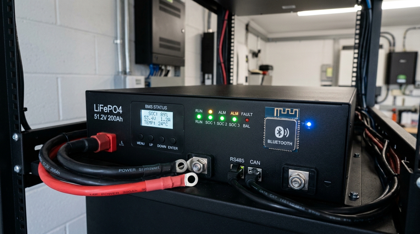
My batteries stopped charging one winter morning — the BMS had a low-temperature cutoff at 32°F. The garage had dropped to 28°F overnight, and the BMS silently disconnected the charge path. Battery voltage read fine (80% SOC), the charge controller showed PV voltage, but zero current was flowing. No error code, no warning. The BMS just quietly said “no” to incoming charge.
What Is a BMS Lockout?
The Battery Management System (BMS) in every LiFePO4 battery protects the cells from conditions that could damage them or create a safety hazard. The BMS can disconnect the charge path, the discharge path, or both — independently.
Common BMS Lockout Triggers
- Low temperature (charge direction only). Most LiFePO4 BMS units cut charging below 0°C (32°F). Charging lithium cells below freezing causes lithium plating on the anode, which permanently damages capacity and creates internal short-circuit risk. This is a safety-critical cutoff — do not try to bypass it.
- High temperature. BMS cuts both charge and discharge above ~55-60°C (130-140°F).
- Cell over-voltage. If any single cell exceeds ~3.65V, the BMS cuts charging. This can happen during cell imbalance when one cell fills faster than others.
- Cell under-voltage. If any cell drops below ~2.5V, the BMS cuts discharge (and sometimes charge too). A deeply depleted battery may need a low-current “wake-up” charge to recover.
- Over-current. The BMS cuts discharge if current exceeds its rating. This is a discharge-side issue, not a charging issue, but it’s worth knowing.
How to Diagnose
- Check BMS status. If your battery has Bluetooth monitoring (most quality LiFePO4 batteries sold since 2024 do), open the app and look at:
- Individual cell voltages — are they balanced (within 0.02V of each other)?
- Temperature readings — is the battery above freezing?
- BMS status flags — does it show charge disabled, discharge disabled, or any fault?
- No Bluetooth? Measure the battery terminal voltage and compare to what you’d expect for the SOC. If terminal voltage reads 0V but you know the battery has charge, the BMS has disconnected both paths. Some BMS units have a reset button or require a brief external charge to restart.
- Check for a BMS reset procedure. Some BMS units, after a lockout event, require you to apply a charge source briefly to “wake” the BMS. Connect a charger (even a small 5A bench charger) to the battery terminals. If the BMS reconnects after a few seconds, it was in a protection state.
Fixes
- Cold temperature: Warm the battery above 40°F (5°C) before attempting to charge. Options: move batteries indoors temporarily, install a heating pad with thermostat, or buy batteries with built-in heating (the EG4 LL-S has this feature — see the best LiFePO4 batteries comparison).
- Cell imbalance: Allow the BMS to top-balance by charging to absorb voltage and holding it there for several hours. This gives the BMS time to balance cells. If imbalance is severe (>0.1V between cells), you may need to manually top-balance the cells — a process covered in the DIY LiFePO4 battery bank guide.
- Deep discharge: Apply a low-current charge (1-5A) to bring cell voltages above the BMS reconnect threshold, then switch to normal charging.
Step 9: Failed Component Identification
If you’ve worked through Steps 1-8 and the battery still isn’t charging, you likely have a failed component. Here’s how to narrow it down.
Charge Controller Failure
Symptoms: PV voltage present at input terminals, battery voltage present at battery terminals, settings correct, no BMS lockout — but zero current flows.
Test: Bypass the charge controller temporarily by connecting a different charge source (grid charger, generator charger) directly to the battery. If the battery charges from the alternate source, the charge controller has failed.
Most charge controller failures I’ve seen are caused by PV over-voltage (connecting panels with voltage exceeding the controller’s maximum input — this usually kills the controller instantly and permanently) or lightning-induced surges.
Solar Panel Failure
Symptoms: One or more panels producing significantly less voltage than rated, or zero voltage.
Test: Disconnect the string and measure each panel individually. Compare Voc readings. A dead panel reads 0V. A failing panel reads significantly below its rated Voc (more than 20% below, in good sunlight).
Panel failure is relatively rare. Junction box solder joint failure, cracked cells from physical damage or manufacturing defect, and delamination from moisture intrusion are the most common panel failure modes. If a panel is under warranty and tests significantly below spec, contact the manufacturer.
Wiring Failure
Symptoms: Voltage present at one end of a wire run but not the other.
Test: Set your multimeter to continuity mode. Disconnect both ends of the suspect wire and test continuity. No beep = broken wire. If you measure resistance instead of clean continuity, you may have a damaged conductor with only a few strands still connected — that wire needs replacing.
The Diagnostic Flowchart (Summary)
For quick reference, here’s the entire process in condensed form:
- Sunlight? No → Wait for sun. Yes → Step 2.
- Panel Voc normal? No → Check MC4s, fuses, individual panels (Step 6). Yes → Step 3.
- Charge controller sees PV? No → Wiring issue between panels and controller (Step 6). Yes → Step 4.
- Battery already full? Yes → No problem. Float is normal. No → Step 5.
- Settings correct? No → Fix settings (Step 5). Yes → Step 6.
- All connections tight, fuses intact? No → Fix connections. Yes → Step 7.
- Voltage drop acceptable? No → Upgrade wire gauge. Yes → Step 8.
- BMS locked out? Yes → Address trigger (temp, imbalance, deep discharge). No → Step 9.
- Failed component → Identify and replace (charge controller, panel, or wiring).
Preventing Future Charging Problems
Here’s what keeps charging reliable long term:
- Install a temperature sensor on your battery bank and configure your charge controller to read it. This prevents cold-weather charging damage and eliminates mysterious BMS lockouts.
- Use appropriately sized wire. Spending an extra $50 on heavier gauge cable during installation saves you from chronic underperformance and frustrating troubleshooting sessions for the life of the system.
- Check MC4 connections annually. Pull apart, inspect, reconnect. Takes 10 minutes. Prevents corrosion-related failures.
- Set charge parameters correctly from day one. Refer to your battery manufacturer’s exact specifications. If you’re building a system for the first time, the getting started guide walks through this process.
- Monitor your system. Even a basic charge controller with a daily kWh counter lets you spot downward trends before they become zero-production emergencies. If yesterday’s clear-sky production was 25 kWh and today’s is 15 kWh under similar conditions, something changed — investigate now rather than waiting until you’re at 0 kWh.
If you’ve followed this entire guide and your system still isn’t charging, gather your findings (panel voltage, controller readings, battery voltage, BMS status, settings screenshots) before reaching out for help. Actual multimeter readings get you answers — “it’s not working” gets you guesses.
Frequently Asked Questions
Why is my solar battery not charging?
The most common causes are: wrong time of day or weather (cloudy skies cut output 60-80%), a tripped breaker or blown fuse, incorrect charge controller settings for your battery type, or a BMS lockout from cold temperature or cell imbalance. Work through the diagnostics from panels down to battery.
What does it mean when my charge controller shows Float?
Float mode means your battery is fully charged and the controller is providing minimal maintenance current. This is normal, not a fault. If your battery charged fully yesterday and you did not use much power overnight, the controller enters float quickly in the morning.
Why did my LiFePO4 battery stop charging in cold weather?
LiFePO4 batteries cannot be charged below 0 degrees C (32 degrees F) without permanent damage. The BMS silently disconnects the charge path when temperature drops below its cutoff. Solutions include warming the battery above 40 degrees F, using batteries with built-in heating, or adding a heating pad with thermostat.
How do I test if my solar panels are working?
Set a multimeter to DC voltage and measure at the panel's MC4 connectors. Compare the reading to the panel's rated Voc from the spec sheet. For a series string, add up each panel's Voc. A reading within 5-10% of rated Voc means the panels are working. Zero volts means a broken connection, blown fuse, or open disconnect switch.
Can wrong charge controller settings prevent battery charging?
Yes. A charge controller set to lead-acid profile when connected to LiFePO4 batteries uses wrong voltage setpoints, often stopping charge too early. Always set the correct battery type and enter the exact absorption and float voltage from your battery manufacturer's specifications.
Anthony
Solar homeowner, EV driver, and DIY builder. Using solar to power a large part of my home.
Get build guides in your inbox
Weekly solar builds, product tests, and technical deep-dives.
Subscribe Free