Solar Wire Gauge Chart: Complete AWG Reference for 12V, 24V, and 48V Systems
Quick answer: For a 12V system running 30A over 10 feet one-way, you need 6 AWG copper wire to keep voltage drop under 3%. For 24V at the same current and distance, 8 AWG works. For 48V, 10 AWG is sufficient. The tables below cover every common scenario — bookmark this page.
Why Wire Sizing Matters More Than You Think
Undersized wire wastes energy as heat. In a 12V system, every tenth of a volt lost to resistance is a meaningful percentage of your total voltage. A common mistake on small builds: running 10 AWG wire on a 30A, 15-foot circuit at 12V — voltage drop eats almost 8% of the power. Swapping to 6 AWG fixes it immediately.
Oversized wire wastes money but causes no problems. Undersized wire causes heat buildup, energy loss, fire hazards, and can prevent your charge controller from functioning correctly. When in doubt, go one size up.
Use our Wire Gauge Calculator to plug in your exact specs and get a recommendation instantly.
How to Read These Tables
All tables assume:
- Copper wire (aluminum requires roughly 2 sizes larger)
- One-way distance — measure from source to load, not round-trip. The formulas already account for the return path.
- 3% maximum voltage drop — this is the standard I recommend for solar DC circuits. NEC allows up to 5% total for feeder + branch, but 3% keeps you in a comfortable margin.
- 75°C rated wire (THWN-2 / USE-2) — standard for solar installations
12V System Wire Gauge Chart
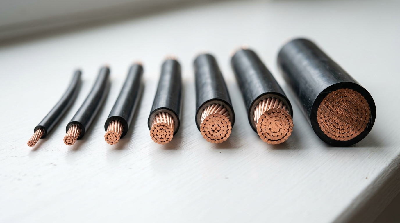
12V systems demand the thickest wire because the current is highest for any given wattage. A 600W load at 12V draws 50A. That same load at 48V draws only 12.5A.
| Current (A) | 5 ft | 10 ft | 15 ft | 20 ft | 25 ft | 30 ft |
|---|---|---|---|---|---|---|
| 10 | 14 AWG | 12 AWG | 10 AWG | 10 AWG | 8 AWG | 8 AWG |
| 15 | 12 AWG | 10 AWG | 8 AWG | 8 AWG | 6 AWG | 6 AWG |
| 20 | 10 AWG | 8 AWG | 8 AWG | 6 AWG | 6 AWG | 4 AWG |
| 30 | 8 AWG | 6 AWG | 6 AWG | 4 AWG | 4 AWG | 2 AWG |
| 40 | 8 AWG | 6 AWG | 4 AWG | 4 AWG | 2 AWG | 2 AWG |
| 50 | 6 AWG | 4 AWG | 4 AWG | 2 AWG | 2 AWG | 1 AWG |
| 60 | 6 AWG | 4 AWG | 2 AWG | 2 AWG | 1 AWG | 1/0 AWG |
| 80 | 4 AWG | 2 AWG | 2 AWG | 1 AWG | 1/0 AWG | 2/0 AWG |
| 100 | 4 AWG | 2 AWG | 1 AWG | 1/0 AWG | 2/0 AWG | 3/0 AWG |
Key takeaway for 12V: If your one-way run exceeds 15 feet and you’re pulling more than 30A, you’re looking at 4 AWG or thicker. This is a big reason I recommend 24V or 48V for anything beyond a small shed system. If you’re building a 48V LiFePO4 battery bank, the cable runs from battery to inverter are where proper sizing matters most — see our DIY LiFePO4 battery bank guide for specific recommendations.
24V System Wire Gauge Chart
Doubling the voltage halves the current for the same wattage, which means significantly smaller (and cheaper) wire.
| Current (A) | 5 ft | 10 ft | 15 ft | 20 ft | 25 ft | 30 ft |
|---|---|---|---|---|---|---|
| 10 | 16 AWG | 14 AWG | 12 AWG | 12 AWG | 10 AWG | 10 AWG |
| 15 | 14 AWG | 12 AWG | 10 AWG | 10 AWG | 10 AWG | 8 AWG |
| 20 | 14 AWG | 10 AWG | 10 AWG | 8 AWG | 8 AWG | 8 AWG |
| 30 | 10 AWG | 8 AWG | 8 AWG | 6 AWG | 6 AWG | 6 AWG |
| 40 | 10 AWG | 8 AWG | 6 AWG | 6 AWG | 4 AWG | 4 AWG |
| 50 | 8 AWG | 6 AWG | 6 AWG | 4 AWG | 4 AWG | 4 AWG |
| 60 | 8 AWG | 6 AWG | 4 AWG | 4 AWG | 4 AWG | 2 AWG |
| 80 | 6 AWG | 4 AWG | 4 AWG | 2 AWG | 2 AWG | 2 AWG |
| 100 | 6 AWG | 4 AWG | 2 AWG | 2 AWG | 1 AWG | 1 AWG |
48V System Wire Gauge Chart
48V is standard for larger residential systems and is what most modern hybrid inverters use. The wire savings alone make it worth choosing 48V when you have the option.
| Current (A) | 5 ft | 10 ft | 15 ft | 20 ft | 25 ft | 30 ft |
|---|---|---|---|---|---|---|
| 10 | 18 AWG | 16 AWG | 14 AWG | 14 AWG | 12 AWG | 12 AWG |
| 15 | 16 AWG | 14 AWG | 14 AWG | 12 AWG | 12 AWG | 10 AWG |
| 20 | 16 AWG | 14 AWG | 12 AWG | 12 AWG | 10 AWG | 10 AWG |
| 30 | 14 AWG | 10 AWG | 10 AWG | 10 AWG | 8 AWG | 8 AWG |
| 40 | 12 AWG | 10 AWG | 10 AWG | 8 AWG | 8 AWG | 6 AWG |
| 50 | 10 AWG | 8 AWG | 8 AWG | 8 AWG | 6 AWG | 6 AWG |
| 60 | 10 AWG | 8 AWG | 8 AWG | 6 AWG | 6 AWG | 6 AWG |
| 80 | 8 AWG | 6 AWG | 6 AWG | 6 AWG | 4 AWG | 4 AWG |
| 100 | 8 AWG | 6 AWG | 4 AWG | 4 AWG | 4 AWG | 2 AWG |
See the difference? At 48V/30A over 20 feet, you only need 10 AWG. At 12V/30A over 20 feet, you need 4 AWG. That’s a massive cost and handling difference.
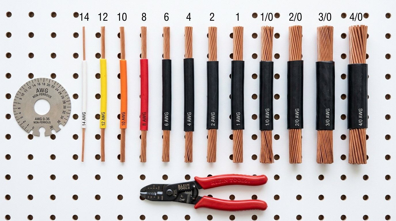
NEC Ampacity Ratings for Copper Wire
These are the maximum continuous current ratings per NEC Table 310.16 for copper conductors at 30°C (86°F) ambient temperature. These limits apply regardless of voltage drop — even if your voltage drop calculation says a smaller wire is fine, you cannot exceed the ampacity rating.
| AWG | 60°C (TW) | 75°C (THWN) | 90°C (THWN-2, USE-2) |
|---|---|---|---|
| 14 | 15A | 20A | 25A |
| 12 | 20A | 25A | 30A |
| 10 | 30A | 35A | 40A |
| 8 | 40A | 50A | 55A |
| 6 | 55A | 65A | 75A |
| 4 | 70A | 85A | 95A |
| 3 | 85A | 100A | 115A |
| 2 | 95A | 115A | 130A |
| 1 | 110A | 130A | 145A |
| 1/0 | 125A | 150A | 170A |
| 2/0 | 145A | 175A | 195A |
| 3/0 | 165A | 200A | 225A |
| 4/0 | 195A | 230A | 260A |
Important: NEC 240.4(D) limits overcurrent protection for small conductors: 14 AWG to 15A, 12 AWG to 20A, and 10 AWG to 30A — regardless of the higher ampacities shown above. These OCPD limits effectively cap what you can run on these wire sizes. Additionally, NEC requires that you use the 75°C column for termination ratings unless your terminals are specifically rated for 90°C. Most breakers, lugs, and bus bars are rated at 75°C. You can use the 90°C ampacity for derating calculations (more on that below), but the final derated value still can’t exceed the 75°C column.
Temperature Derating Factors
If your ambient temperature exceeds 30°C (86°F) — which is common in attics, on rooftops, and inside conduit exposed to direct sun — you must derate the ampacity. Multiply the base ampacity by these factors:
| Ambient Temp | 60°C Wire | 75°C Wire | 90°C Wire |
|---|---|---|---|
| 31-35°C (87-95°F) | 0.91 | 0.94 | 0.96 |
| 36-40°C (96-104°F) | 0.82 | 0.88 | 0.91 |
| 41-45°C (105-113°F) | 0.71 | 0.82 | 0.87 |
| 46-50°C (114-122°F) | 0.58 | 0.75 | 0.82 |
| 51-55°C (123-131°F) | 0.41 | 0.67 | 0.76 |
| 56-60°C (132-140°F) | — | 0.58 | 0.71 |
Real-world example: Consider conduit running across a sun-exposed roof in a hot climate. In summer, the conduit interior can easily hit 50°C. A 6 AWG THWN-2 wire has a 90°C rating of 75A, but with the derating factor of 0.82, the adjusted ampacity is 75 × 0.82 = 61.5A. Since the 75°C column for 6 AWG is 65A, the derated value of 61.5A is the governing limit.
Conduit Fill Derating
Running multiple current-carrying conductors in the same conduit adds another derating factor on top of the temperature derating:
| Number of Current-Carrying Conductors | Derating Factor |
|---|---|
| 1-3 | 1.00 (no derating) |
| 4-6 | 0.80 |
| 7-9 | 0.70 |
| 10-20 | 0.50 |
Note: Equipment grounding conductors and neutrals that carry only unbalanced current don’t count as current-carrying conductors.
Most residential solar runs only have 2-3 current-carrying conductors per conduit, so this rarely comes into play. But if you’re running multiple string circuits through the same conduit from a rooftop array, pay attention.
Understanding Voltage Drop
Voltage drop is the reduction in voltage as current flows through wire resistance. The formula is straightforward:
Voltage Drop (V) = (2 × Length × Current × Resistance per foot) / 1000
Where resistance per foot comes from the wire’s AWG size:
| AWG | Resistance (Ω per 1000 ft) |
|---|---|
| 14 | 3.14 |
| 12 | 1.98 |
| 10 | 1.24 |
| 8 | 0.778 |
| 6 | 0.491 |
| 4 | 0.308 |
| 2 | 0.194 |
| 1 | 0.154 |
| 1/0 | 0.122 |
| 2/0 | 0.0967 |
| 3/0 | 0.0766 |
| 4/0 | 0.0608 |
Worked Example
Let’s say you have a 12V system, 30A charge controller, 15 feet one-way from panels to controller, and you’re considering 8 AWG wire.
Voltage Drop = (2 × 15 × 30 × 0.778) / 1000 = 0.70V
Percentage = 0.70 / 12 × 100 = 5.8%
That’s too high. Almost 6% of your power is turning into heat in the wire. At 30A × 0.70V, that’s 21 watts of continuous waste. Over a 6-hour solar day, you’re throwing away 126 Wh daily — about 46 kWh per year.
With 6 AWG wire:
Voltage Drop = (2 × 15 × 30 × 0.491) / 1000 = 0.44V
Percentage = 0.44 / 12 × 100 = 3.7%
Better, but still above 3%. To get under 3%, you’d need 4 AWG:
Voltage Drop = (2 × 15 × 30 × 0.308) / 1000 = 0.28V
Percentage = 0.28 / 12 × 100 = 2.3%
That’s where you want to be. Don’t want to do this math every time? Use the Wire Gauge Calculator — plug in your numbers and get the answer in seconds.
When to Upsize Your Wire
The tables above give minimums for 3% voltage drop. Here’s when you should go at least one AWG size larger:
Long Runs (Over 30 Feet)
Any run over 30 feet at 12V deserves extra attention. I’ve seen people run 50-foot cables from a ground-mounted array to a shed and wonder why their system underperforms. At those distances with 12V, you’re often looking at 2/0 or larger wire — at which point you should seriously consider running the panels at a higher voltage and stepping down closer to the batteries.
High Ambient Temperature
If your wire runs through an attic, unshaded conduit on a roof, or a hot engine compartment (RV builds), upsize. The resistance of copper increases roughly 0.4% per degree Celsius above 20°C. A wire running at 60°C has about 16% more resistance than the same wire at 20°C.
Conduit Fill Over 40%
Wires in conduit dissipate heat slower than wires in free air. If you’re packing conduit close to the 40% fill limit, upsizing one gauge gives you both thermal headroom and easier pulling.
Future Expansion
Planning to add panels or increase your load? Sizing wire for your future system now is dramatically cheaper than re-running wire later. When I built my system, I ran 4 AWG for a circuit that only needed 6 AWG, knowing I’d be doubling my panel count within a year. That $40 extra in copper saved me a full day of rewiring.
Fuse and Breaker Sizing: The NEC 125% Rule
NEC 240.4 and NEC 690.8 require that overcurrent protection devices (fuses or breakers) for continuous loads be rated at 125% of the maximum continuous current. For a deep dive into fuse and breaker selection, see our solar fuses and breakers overcurrent protection guide. Solar circuits are always considered continuous loads because they can produce rated current for 3+ hours at a stretch.
How to Apply the Rule
- Determine the maximum circuit current — for solar panels, this is the short-circuit current (Isc) of the string
- Multiply by 1.25 — this gives you the minimum fuse/breaker rating
- Select the next standard size up — standard fuse/breaker sizes are 15, 20, 25, 30, 35, 40, 45, 50, 60, 70, 80, 90, 100A
- Verify the wire ampacity — the wire must be rated for at least the fuse/breaker size
Example: Your panel string has an Isc of 10.5A.
- 10.5 × 1.25 = 13.1A
- Next standard size up = 15A fuse
- Wire must be rated for at least 15A → minimum 14 AWG (at 75°C)
For battery circuits, use the maximum charge or discharge current as your starting point.
Common mistake I see: People size the fuse to match the wire instead of sizing the wire to handle the fuse. The fuse protects the wire. If your calculation calls for a 30A fuse, your wire must handle 30A continuous — even if the normal operating current is only 20A.
Wire Types for Solar Installations
Not all wire is rated for outdoor or solar use. Here’s what to actually buy:
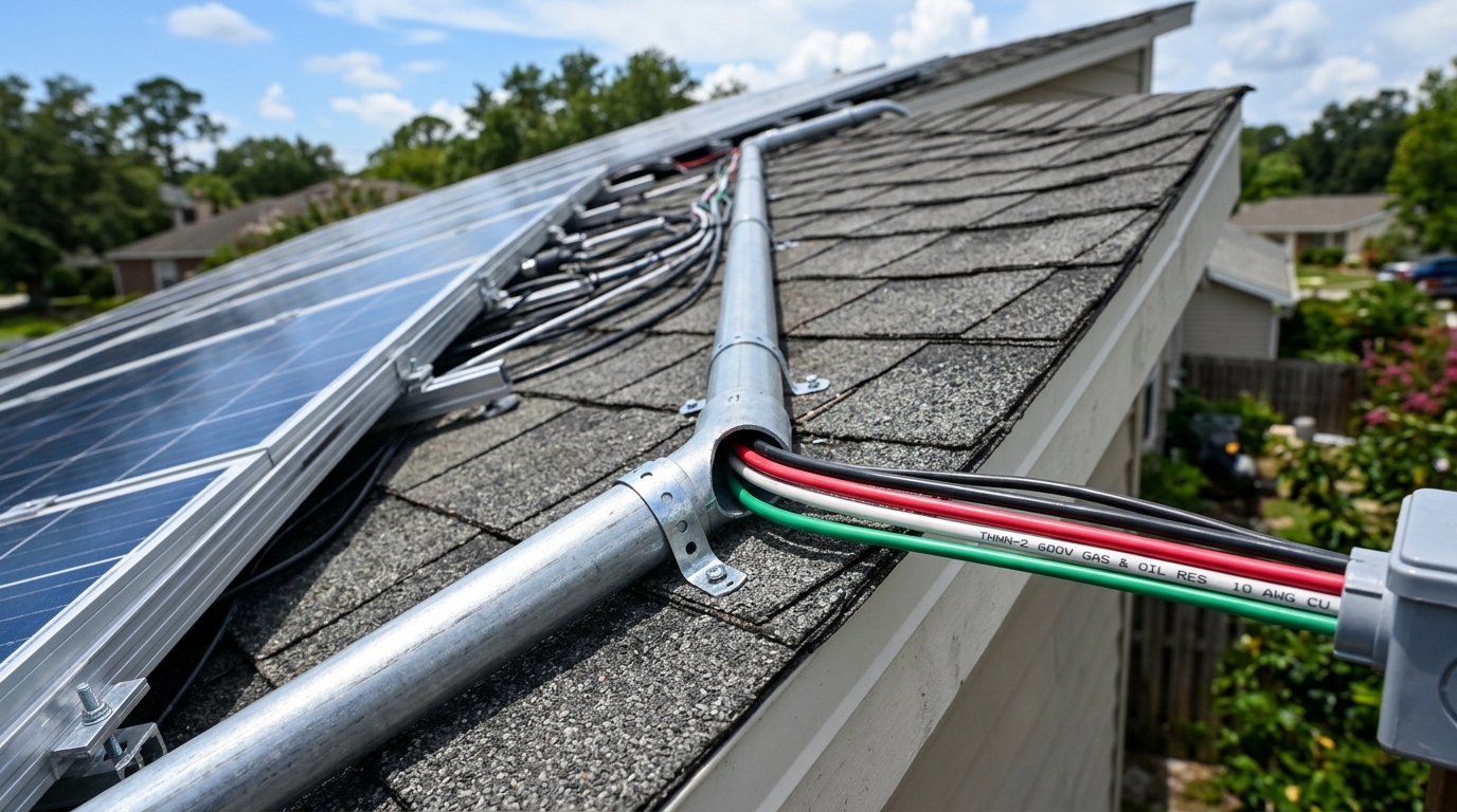
PV Wire (USE-2 / PV Wire)
- Required for exposed wiring between panels and junction boxes
- Rated for direct sunlight exposure (UV resistant)
- 90°C wet/dry rating
- Usually 600V or 1000V rated
- This is what you want for any rooftop or ground-mount exposed runs
THWN-2 / THHN
- Suitable for conduit runs (not exposed to direct sunlight unless in UV-rated conduit)
- 90°C dry, 75°C wet rating
- Common and affordable
- My go-to for indoor runs, conduit runs from junction box to charge controller/inverter
Welding Cable
- Highly flexible, good for battery connections
- NOT NEC compliant for permanent installation in most jurisdictions
- Fine for portable/temporary setups, RV battery connections
- I use it for the short jumps between batteries in my bank because the flexibility makes tight spaces manageable
MC4 Pigtail Wire
- Pre-terminated with MC4 connectors
- Usually PV wire, but always verify the rating
- Convenient for panel-to-panel connections and home runs to a junction box
Quick Reference: Common Solar Circuits
Here are the most frequent wiring scenarios I run into, with my recommended wire gauges assuming runs under 15 feet one-way:
| Circuit | Typical Voltage | Typical Current | Recommended AWG |
|---|---|---|---|
| Panel string to combiner box | System voltage | 10-12A per string | 10 AWG PV wire |
| Combiner to charge controller | System voltage | 20-60A | 6-4 AWG THWN-2 |
| Charge controller to battery | Battery voltage | 30-80A | 4-2 AWG THWN-2 |
| Battery to inverter | Battery voltage | 80-200A | 2/0-4/0 AWG |
| Battery interconnects | Battery voltage | 80-200A | 2/0-4/0 AWG (or busbar) |
| Inverter to AC panel | 120/240V AC | 15-50A | 14-6 AWG per NEC |
Pro tip: The battery-to-inverter run is almost always the fattest wire in the system. A 3000W inverter at 12V draws 250A — that’s 4/0 territory. At 48V, the same inverter draws only 62.5A — comfortable in 4 AWG. This is the single strongest argument for 48V systems.
Summary: The Rules I Follow
After wiring several systems, these are the rules that have served me well:
- Always calculate for 3% voltage drop maximum — don’t rely on rules of thumb
- Always check NEC ampacity — voltage drop and ampacity are separate checks; the wire must pass both
- Always apply the 125% rule for fuse/breaker sizing on continuous circuits
- Always derate for temperature if wire runs through hot environments
- When in doubt, upsize one gauge — copper is cheaper than troubleshooting
- Run higher voltage when possible — 48V systems use dramatically less copper than 12V
For custom calculations, the Wire Gauge Calculator handles all of this automatically. And if you’re designing a new system from scratch, start with the Solar System Sizer to figure out what you’re working with before you buy a single foot of wire.
Want to estimate the full cost of your system including wiring? Try the Cost Estimator — it factors in wire costs based on your system layout. And if your panels aren’t producing what you expected, incorrect wire sizing is one of the most common culprits — our solar panel troubleshooting guide walks through how to diagnose voltage drop and other output issues.
For help deciding how to wire your panels before you worry about cable gauge, check out our series vs parallel wiring guide — the configuration you choose directly affects the current (and therefore wire size) in each run.
Frequently Asked Questions
What size wire do I need for a 30 amp solar system?
It depends on your voltage and distance. At 12V over 10 feet one-way, you need 6 AWG. At 24V same distance, 8 AWG works. At 48V, 10 AWG is sufficient. Always calculate for both ampacity and 3% maximum voltage drop, then use whichever requires the larger wire.
What is the NEC 125% rule for solar wire sizing?
NEC 240.4 and 690.8 require that wires and fuses for continuous solar circuits be rated at 125% of the maximum continuous current. Solar circuits are always considered continuous loads because they can produce rated current for 3+ hours.
Why does a 48V solar system need thinner wire than 12V?
Higher voltage means lower current for the same wattage. A 3,000W load at 12V draws 250A (requiring 4/0 AWG cable), while the same load at 48V draws only 62.5A (comfortable in 4 AWG). This is the single strongest argument for 48V systems.
What type of wire should I use for outdoor solar runs?
Use PV wire (USE-2 rated) for any exposed outdoor run. It is rated for 90 degrees C, UV resistant, and sunlight resistant. THWN-2 is acceptable inside conduit but is not UV resistant for exposed runs. Never use THHN alone outdoors.
How do I calculate voltage drop for solar wiring?
Use the formula: Voltage Drop = (2 x Length x Current x Wire Resistance per foot) / 1000. Keep the percentage drop under 3% of your system voltage. For example, 30A over 15 feet of 6 AWG at 12V gives 0.44V drop (3.7%) — too high, so you need 4 AWG.
Anthony
Solar homeowner, EV driver, and DIY builder. Using solar to power a large part of my home.
Get build guides in your inbox
Weekly solar builds, product tests, and technical deep-dives.
Subscribe Free