NEC Code Requirements for Residential Solar: A DIY Reference
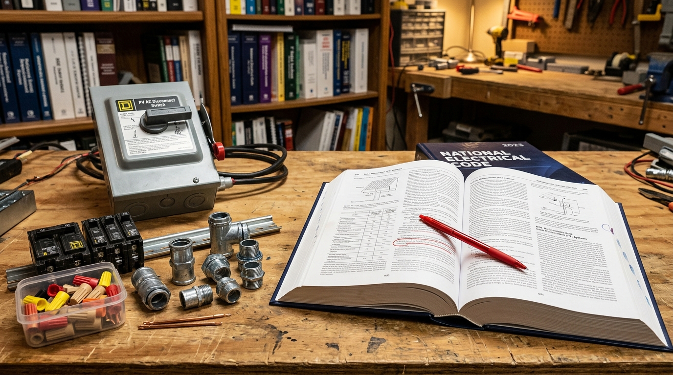
Short answer: Residential solar installations in the US must follow NEC Article 690 (Solar Photovoltaic Systems). The big requirements: rapid shutdown within 30 seconds, equipment grounding on all exposed metal, overcurrent protection on every ungrounded conductor, wire sizing based on ampacity (not just voltage drop), and specific labels at the disconnect, combiner box, and main panel. Most jurisdictions now enforce NEC 2023, and NEC 2026 is rolling out. If you skip any of these, you will fail inspection — I speak from experience.
Why NEC Compliance Matters Even for DIY
I failed my first solar inspection. The system worked fine — panels producing, batteries charging, inverter humming along. But I was missing two labels: one on the AC disconnect and one on the main service panel identifying the solar backfeed breaker. The inspector didn’t even look at my wiring before flagging those.
That taught me that NEC compliance isn’t about whether your system works. It’s about whether your system is documentably safe. Inspectors have a checklist and they go through it methodically. Knowing what’s on that checklist before you start saves rework, re-inspection fees, and frustration.
This guide covers the NEC requirements that apply to typical residential rooftop and ground-mount solar PV systems. I’m focusing on NEC 2023 (which most jurisdictions currently enforce) with notes on NEC 2026 changes where they affect residential installations. If your local authority having jurisdiction (AHJ) is still on NEC 2020 or earlier, some requirements may differ — always check with your local building department.
For a complete beginner’s overview of system design, start with the getting started guide and come back here when you’re ready to plan your installation for code compliance.
Article 690: Solar PV Systems — The Key Sections
NEC Article 690 is the primary code section for solar PV, published by the National Fire Protection Association (NFPA). Here’s what each part covers in practical terms.
690.1 — Scope
Article 690 covers everything from the solar panels to the point of connection with other systems (your main panel, battery bank, or utility interconnection). If it carries current generated by a solar panel, 690 applies.
690.7 — Maximum Voltage
Your PV system voltage is calculated using the coldest expected temperature at your location, not standard test conditions (STC). Cold panels produce higher voltage than their nameplate Voc. NEC 690.7 requires you to calculate worst-case voltage using either:
- Temperature correction factors from NEC Table 690.7(A), or
- The manufacturer’s Voc temperature coefficient applied to the record low temperature for your location
For example, three 320W panels in series with a nameplate Voc of 41.2V each give 123.6V at STC. At -18°C (a typical design low for southern New England), the corrected Voc rises to around 141V. That’s the number you’d use for sizing the charge controller’s input rating and selecting the DC disconnect.
This is directly relevant to choosing your panel wiring configuration — the series vs parallel guide walks through how string voltage affects your component selection.
690.8 — Circuit Sizing and Current
NEC requires that PV circuit conductors and overcurrent devices be sized based on 125% of the maximum circuit current. For a panel string with an Isc (short circuit current) of 10.2A, your minimum conductor ampacity and fuse rating must handle 10.2 × 1.25 = 12.75A.
This 125% factor accounts for continuous duty — solar circuits operate at or near maximum current for hours at a time, and NEC defines any load operating for 3+ hours as continuous.
The 125% factor applies to:
- Wire ampacity
- Overcurrent device (fuse or breaker) rating
- Disconnect switch rating
- Charge controller and inverter input current ratings
690.9 — Overcurrent Protection
Every ungrounded conductor in a PV system needs overcurrent protection. In practice, this means:
PV source circuits (panel strings): Fuses on each string if you have multiple strings in parallel. If you have a single string, the charge controller or inverter typically provides the overcurrent protection, but check with your AHJ — some require a fuse or breaker even on single-string systems.
PV output circuits (from combiner to controller/inverter): Fuse or breaker rated per 690.8. This is typically in the combiner box.
Battery circuits: Fuse or breaker between the battery bank and the inverter/charge controller. This is the one that protects against a dead short on your battery cables — which can deliver thousands of amps instantaneously on a LiFePO4 bank. Our solar fuses and breakers guide covers Class T fuse sizing and the full 156% rule in detail.
Inverter output circuits: Standard AC overcurrent protection per NEC Article 240.
I use inline fuses for my PV strings (20A fuses for 10.2A Isc panels — 10.2 × 1.56 = 15.9A, next standard fuse size up is 20A) and a 175A Class T fuse on the battery bank. Class T fuses are the standard for battery protection because they have the interrupt rating to handle the massive fault current a battery bank can deliver.
690.11 — Arc-Fault Circuit Protection (DC)
NEC 2023 requires DC arc-fault circuit interrupters (AFCI) on PV systems with DC circuits operating above 80V. This is a significant requirement that catches many DIY builders off-guard.
Options for compliance:
- An inverter with built-in DC AFCI (most modern string inverters include this)
- A standalone AFCI device in the DC circuit
- A charge controller with built-in arc fault detection (like the Midnite Classic 150)
- Microinverters or DC optimizers that reduce module-level voltage below 80V
If your system runs below 80V DC — for example, a single panel or two panels in parallel feeding a 12V or 24V charge controller — you may be exempt from this requirement. But confirm with your AHJ.
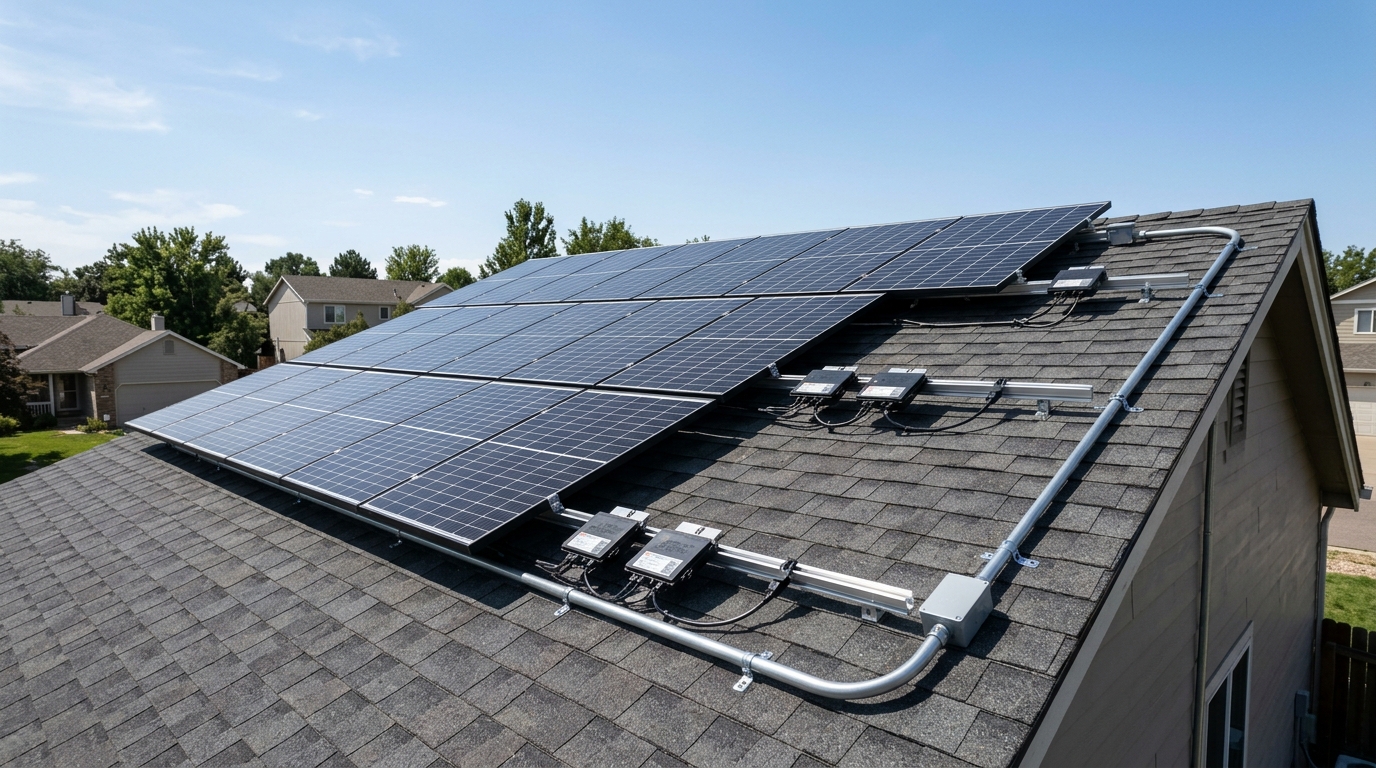
690.12 — Rapid Shutdown
This is the requirement that gets the most attention, and it’s been tightened significantly in NEC 2023.
What it requires: Within 30 seconds of initiating rapid shutdown, conductors outside the array boundary must be de-energized to 30V or less, and conductors within the array boundary must be de-energized to 80V or less within 30 seconds. NEC 2017 defined the boundary as 1 foot from the array; NEC 2020 and 2023 tightened this to require module-level shutdown capability for the within-array requirement.
In plain language: When a firefighter hits the rapid shutdown switch, the high-voltage DC wiring from your roof needs to go dead within 30 seconds. This prevents electrocution from energized conductors on or near a burning building.
How to comply:
- Module-level power electronics (MLPEs): Microinverters (Enphase) or DC optimizers (SolarEdge) satisfy rapid shutdown at the module level. Each panel has its own shutdown capability.
- Rapid shutdown devices: Products like Tigo TS4-A-F or APsystems add-on modules mount on each panel and respond to a shutdown signal.
- Some string inverters have integrated rapid shutdown compliant systems.
For DIY off-grid systems not connected to the grid, rapid shutdown requirements may vary by jurisdiction. Some AHJs exempt fully off-grid systems; others require compliance regardless. Ask your building department before assuming you’re exempt.
690.13 — Disconnects
You need disconnecting means (switches or breakers) for:
- PV DC disconnect: Between the array and the inverter/charge controller. Must be rated for DC at the system’s maximum voltage and current. AC-rated switches are NOT acceptable for DC circuits — DC arcs don’t self-extinguish at zero-crossing like AC arcs do.
- Battery disconnect: Between the battery bank and all connected equipment.
- AC disconnect: Between the inverter output and the main panel or utility connection. For grid-tied systems, this must be a lockable disconnect accessible to the utility.
- Equipment disconnect: Each piece of equipment (inverter, charge controller) must have a disconnect means within sight of the equipment.
All disconnects must be lockable in the open position. In my installation, I have a DC-rated 150V disconnect between the combiner box and the charge controller, a 175A battery disconnect at the battery bank, and a 60A AC disconnect between the inverter and the sub-panel.
Grounding Requirements
NEC distinguishes between equipment grounding and system grounding, and solar installations involve both.
Equipment Grounding (690.43)
All exposed metal parts — panel frames, mounting rails, combiner box enclosures, disconnect enclosures, inverter chassis, conduit — must be bonded to the equipment grounding conductor (EGC). This protects against shock if a conductor faults to the frame.
For panel mounting, you can use:
- Grounding lugs on each panel frame, connected with bare or green insulated copper
- Grounding washers (WEEBs) that bite through the anodized aluminum when you bolt the panel to the rail, creating a bond without separate lugs
- Listed grounding clips specific to your racking system
I use WEEBs on my rail-mounted panels — they’re faster to install and listed for the purpose. Each rail section bonds to the next, and the end of the rail run connects to a #6 bare copper equipment grounding conductor that runs back to the grounding bar in my sub-panel.
System Grounding (690.41)
For systems over 50V, NEC requires a system ground — one conductor of the PV circuit connected to ground. This is typically the negative conductor. However, many modern inverters and charge controllers are designed for ungrounded (floating) PV arrays, and NEC 690.35 provides requirements for ungrounded systems.
If your system uses a grounded configuration, you need a ground fault protection device (GFPD) per 690.41(B). If your system is ungrounded, you need a ground fault detector/indicator per 690.35(C).
Check your inverter or charge controller manual — it will specify whether it requires a grounded or ungrounded PV array.
Wire Sizing Per NEC
NEC wire sizing for solar circuits considers two factors, and you must satisfy both:
1. Ampacity (NEC 310)
The wire must have sufficient ampacity (current-carrying capacity) for the circuit current after applying derating factors:
- 125% continuous duty factor (690.8)
- Temperature derating from NEC Table 310.15(B)(1) — wire ampacity drops as ambient temperature rises
- Conduit fill derating from NEC Table 310.15(C)(1) — more wires in a conduit means each wire must be derated
Example: A PV string with Isc of 10.2A on your roof in a location where conduit temperatures reach 60°C:
- 10.2A × 1.25 = 12.75A minimum ampacity required
- At 60°C, 10 AWG THWN-2 has a 90°C base ampacity of 40A. Using the 90°C derating factor of 0.71: 40 × 0.71 = 28.4A. That’s under the 75°C termination limit of 35A, so 28.4A governs — still adequate.
- But if you have 4 current-carrying conductors in that conduit, derate again: 28.4 × 0.80 = 22.7A — still passes
- With 7+ conductors: 28.4 × 0.70 = 19.9A — still passes, but getting tight
That’s a realistic scenario for a roof conduit sitting on dark shingles that easily reaches 60°C on a summer afternoon. 10 AWG THWN-2 works in this case, but there’s not much margin. When in doubt, running 8 AWG gives comfortable headroom.
2. Voltage Drop (Recommended, Not Required)
NEC doesn’t mandate a maximum voltage drop for PV circuits, but recommends keeping it under 3% for branch circuits and 5% total (feeder + branch). The solar wire gauge chart is built around the 3% standard, and the Wire Gauge Calculator lets you plug in exact numbers.
For practical wire sizing, calculate for both ampacity and voltage drop, then use whichever requires the larger wire. On short runs (under 10 feet), ampacity usually governs. On long runs (over 20 feet), voltage drop often requires larger wire than ampacity alone would.
Labeling Requirements (690.56)
This is where my first inspection failed, so I’ve since become thorough about it. NEC requires permanent, weather-resistant labels at multiple points in the system.
Required Labels
1. Main Service Panel (690.56(A)): A label on the main service panel indicating the presence of a PV system, the location of the PV disconnect, and the rated AC output.
Example:
CAUTION: SOLAR PV SYSTEM — FEEDS THIS PANEL AC DISCONNECT LOCATED: [location] RATED OUTPUT: 6,000W / 240V
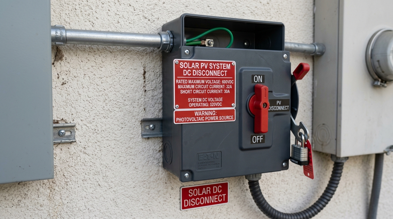
2. PV Disconnect (690.56(B)): Each disconnect must be labeled with its function. The DC disconnect gets:
SOLAR PV DC DISCONNECT MAXIMUM VOLTAGE: [Voc corrected for cold] VDC MAXIMUM CURRENT: [Isc × 1.25] A
3. AC Disconnect (690.56(C)):
SOLAR PV SYSTEM AC DISCONNECT
4. Backfeed Breaker (690.64): If you’re feeding power back to your main panel through a breaker, that breaker must be labeled:
WARNING: SOLAR PV — DO NOT RELOCATE THIS BREAKER THIS BREAKER MUST REMAIN IN THIS POSITION
This prevents someone from moving the breaker to a different slot, which could cause a bus bar overload (the “120% rule” — see below).
5. Rapid Shutdown Initiator (690.56(C)):
SOLAR PV SYSTEM EQUIPPED WITH RAPID SHUTDOWN RAPID SHUTDOWN SWITCH: [location]
6. Battery System (706.10): If you have a battery bank:
ENERGY STORAGE SYSTEM RATED ENERGY: [kWh] RATED VOLTAGE: [nominal voltage] TYPE: Lithium Iron Phosphate (LiFePO4)
Label Specs
Labels must be:
- Durable (UV-resistant for outdoor locations)
- Red background with white text (for certain warning labels)
- Reflective where specified (rapid shutdown labels on NEC 2023)
- Permanently attached (no tape — use adhesive-backed engraved labels or stamped metal)
I buy pre-made NEC solar label kits on Amazon for about $40. They include every label you need and are made of UV-resistant vinyl with permanent adhesive. Absolutely worth it compared to trying to make your own.
The 120% Rule (705.12)
If your system connects to the main panel (grid-tied or hybrid), the total of all power sources feeding the panel bus bar cannot exceed 120% of the bus bar rating.
Calculation: Bus bar rating × 1.20 − main breaker rating = maximum solar backfeed breaker.
Example: 200A bus bar × 1.20 = 240A total. Minus 200A main breaker = 40A maximum solar backfeed breaker.
If your inverter outputs more than 40A at 240V (about 9,600W), you’ll need a line-side connection instead of a load-side backfeed breaker. Line-side connections tap in before the main breaker and have different (more complex) requirements.
For most residential systems under 7,600W, a 40A backfeed breaker on a 200A panel works fine. The backfeed breaker must be installed at the opposite end of the bus bar from the main breaker, permanently affixed (sometimes called the “stab lock” requirement), and labeled.
What Inspectors Actually Look For
I’ve been through three inspections now — one fail and two passes. Here’s the practical checklist most inspectors work through:
Before they go on the roof:
- Permit application matches the installed system (panel count, inverter model, layout)
- Engineering documentation (line diagram, site plan, equipment spec sheets)
- Labels on the main panel, AC disconnect, DC disconnect
- Proper grounding visible at the equipment
- Wire sizing matches the plan
- Overcurrent protection devices match the plan
On the roof:
- Panels match the layout drawing
- Mounting hardware is properly secured (lag bolts into rafters, not just decking)
- Grounding of all metal components
- Conduit is supported at required intervals (within 3 feet of fittings and every 10 feet for EMT per 358.30; every 3 feet for smaller PVC per 352.30)
- Rapid shutdown compliance
- Clearances maintained (fire setback from ridge and edges — varies by jurisdiction)
At the electrical equipment:
- All disconnects operate correctly
- Wire terminations are tight and properly torqued
- Conduit fill doesn’t exceed limits
- Equipment is listed (UL or equivalent) and installed per manufacturer instructions
- Battery area ventilation (for lithium, this is less of a concern than for lead-acid)
Common fail points (based on my experience and what I’ve heard from other DIY builders):
- Missing or incorrect labels (the #1 fail reason)
- Conduit not properly supported
- Missing equipment grounding on mounting rails
- No DC-rated disconnect (using an AC switch on a DC circuit)
- Backfeed breaker in wrong position on bus bar
- Missing rapid shutdown compliance documentation
When Do You Need a Permit?
Almost always. The short answer is that any permanently installed solar PV system connected to a building’s electrical system requires a permit in most US jurisdictions. This includes:
- Grid-tied systems (always require permits)
- Off-grid systems connected to a building’s wiring (almost always require permits)
- Battery energy storage systems (increasingly require permits under NEC Article 706)
Small portable systems — a panel on a stand connected to a battery with no permanent wiring — generally don’t require permits. But the line between “portable” and “permanent” varies by jurisdiction.
Getting the permit: Most building departments want:
- A completed permit application
- A site plan showing panel locations
- A single-line electrical diagram
- Equipment spec sheets (panels, inverter, charge controller)
- A structural analysis (for roof-mounted systems, proving the roof can handle the load)
- An engineer’s stamp (required in some jurisdictions, not all — ask first)
The permit fee ranges from $100-500 depending on your jurisdiction. Some areas charge a flat fee; others charge based on system size or project value.
NEC 2026 Changes Worth Knowing
NEC 2026 is being adopted by jurisdictions starting in late 2025. Key changes for residential solar:
- Enhanced rapid shutdown requirements with stricter module-level shutdown specifications
- Expanded energy storage requirements in Article 706, including more detailed requirements for LiFePO4 and other lithium battery systems
- Updated wire sizing tables reflecting new conductor temperature ratings
- Clearer requirements for hybrid/multimode inverters (like the EG4 6000XP covered in our EG4 review)
If you’re installing in 2026, check which NEC edition your jurisdiction has adopted. Some are still on NEC 2020, most are on NEC 2023, and early adopters are moving to NEC 2026. The jurisdiction’s adopted edition is the one you must follow.
Putting It All Together
Code compliance adds cost and complexity to a DIY solar build, but it’s non-negotiable if you want a permitted, insurable, and safe installation. Budget an extra $200-400 for the label kit, DC-rated disconnects, proper fuses, and grounding hardware that code requires.
Before you buy your first component, sketch out a single-line diagram that includes every disconnect, fuse, grounding conductor, and label point. That diagram becomes your build plan and your permit application. It’s much cheaper to add a disconnect to a drawing than to retrofit one into a finished installation.
The getting started guide walks through system design, and the Wire Gauge Calculator handles the ampacity and voltage drop math. For panel wiring configurations that affect your system voltage and current — and therefore your code compliance requirements — see the panel wiring guide. And make sure your entire installation qualifies for the federal solar tax credit — DIY labor doesn’t count, but all your equipment and materials do.
Frequently Asked Questions
What NEC code applies to residential solar installations?
NEC Article 690 (Solar Photovoltaic Systems) is the primary code section. Article 706 covers energy storage (batteries). Article 705 covers interconnected power production sources. Most jurisdictions currently enforce NEC 2023, with NEC 2026 rolling out.
What is the NEC rapid shutdown requirement for solar?
NEC 690.12 requires that within 30 seconds of initiating rapid shutdown, conductors outside the array boundary must drop to 30V or less, and conductors within the array must drop to 80V or less. This protects firefighters from energized rooftop conductors.
Do I need a permit for DIY solar installation?
Almost always yes. Any permanently installed solar PV system connected to a building's electrical system requires a permit in most US jurisdictions. Grid-tied systems always require permits plus a utility interconnection agreement. Some areas exempt small portable off-grid systems.
What is the NEC 120% rule for solar?
NEC 705.12 limits total power sources feeding a panel bus bar to 120% of its rating. For a 200A panel: 200A x 1.20 = 240A total, minus the 200A main breaker, leaving 40A maximum for a solar backfeed breaker (about 9,600W at 240V).
What are the most common reasons for failing a solar inspection?
The top fail reasons are: missing or incorrect labels (especially on the main panel and disconnects), conduit not properly supported, missing equipment grounding on mounting rails, using AC-rated switches on DC circuits, and backfeed breaker in the wrong bus bar position.
Anthony
Solar homeowner, EV driver, and DIY builder. Using solar to power a large part of my home.
Get build guides in your inbox
Weekly solar builds, product tests, and technical deep-dives.
Subscribe Free