Solar Fuses and Breakers: NEC Overcurrent Protection Guide
Short answer: Every ungrounded conductor in a solar system needs overcurrent protection per NEC 690.9, and every device must be sized using the 156% rule (Isc × 1.25 × 1.25) from NEC 690.8. In practice that means four places fuses and breakers absolutely must live: on each PV source circuit (in the combiner, once you have three or more parallel strings), at the battery bank terminals (MRBF on the post plus a Class T fuse for lithium), on the inverter DC input, and on the AC output to your panel. Use DC-rated devices for DC circuits — always. AC breakers on DC kill people.
Why I Take Overcurrent Protection Seriously
I have a 48V LiFePO4 bank in my garage in Rhode Island. If a wrench falls across the terminals, the short-circuit current is north of 15,000 amps. That’s a welding-arc event that vaporizes copper and sets insulation on fire in the time it takes you to blink.
The only thing standing between “a bad day” and “a house fire” is the fuse on the positive battery terminal. If that fuse isn’t rated to interrupt the available fault current cleanly, it doesn’t just fail to protect — it becomes part of the fire. I learned this when I was researching my own build: ordinary ANL fuses that look beefy on paper have interrupt ratings (AIC) as low as 2,000 amps. A LiFePO4 short laughs at 2,000 amps. You need a Class T, or you need a different battery chemistry.
This article walks through how NEC Article 690 expects you to protect every conductor in a typical DIY solar build — PV source circuits, combiner, inverter input, battery bank, and AC output. I’ll reference specific code sections, but if you want the full code overview first, start with my NEC residential solar reference and come back.
The 156% Rule: NEC 690.8 Current Sizing
Solar is the only part of the NEC that stacks two 125% factors on top of each other, and understanding why saves you from undersizing everything.
NEC 690.8(A) — Maximum Circuit Current. For a PV source circuit, the maximum current is defined as the module’s short-circuit current (Isc) multiplied by 1.25. That first 25% adder exists because real-world irradiance can exceed the 1000 W/m² used at Standard Test Conditions — cloud edge reflections and cold bright days can push actual Isc above nameplate. The code forces you to design for that.
NEC 690.8(B) — Conductor Ampacity and OCPD Size. On top of the 690.8(A) number, you apply a second 1.25 factor because solar circuits are continuous loads (operating at maximum current for three or more hours). That’s the same factor that applies to any continuous load elsewhere in the NEC.
Multiplied together: 1.25 × 1.25 = 1.5625, or 156% of Isc.
Worked example
My 320W panels have an Isc of 10.2A:
- 690.8(A): 10.2 × 1.25 = 12.75A (maximum circuit current)
- 690.8(B): 12.75 × 1.25 = 15.94A (minimum OCPD and conductor ampacity)
- Next standard fuse size up: 20A per NEC 240.4(B), which allows the next standard OCPD size above the calculated ampacity when the conductor is rated accordingly. A 20A fuse requires conductor ampacity of at least 20A — 12 AWG PV wire (rated 25A at 75°C) satisfies this.
The same 156% factor applies to your combiner output, DC feeder to the charge controller, and charge controller input rating. This is also the number you plug into the wire gauge chart when you’re sizing conductors — fuse and wire get sized together, not independently.
NEC 690.9: Where Overcurrent Protection Is Required
Article 690.9 is the rule that says “protect every ungrounded conductor, with these specific exceptions.” In a typical DIY residential build, it lands in these places:
- PV source circuits — each parallel string when you have three or more strings (see the string fuse section below)
- PV output circuit — the feeder between the combiner box and the charge controller or inverter
- Battery DC circuits — both between the battery and the inverter, and between the battery and the charge controller, on the positive conductor
- Inverter AC output — standard breaker per NEC Article 240 in your AC panel
- Any conductor that could be back-fed by another source
The exception that matters for small builds: if you have only one or two PV strings in parallel, the modules themselves act as the overcurrent limit, because the short-circuit current of the other string can’t exceed the back-feed rating of the shorted module. Once you hit three strings, a fault in one can be fed by two others, and you need per-string fuses.
Class T Fuses: The Only Real Option for Lithium
Class T is a specific UL fuse class — physically small, fast-acting, and (critically) rated to interrupt massive fault currents at DC voltages.
| Spec | Class T Rating |
|---|---|
| Voltage rating (DC) | 125V or 160V (varies by model) |
| AIC (interrupt capacity) | 20,000A (some models 50,000A) |
| Speed | Fast-acting |
| Common sizes for solar | 100A, 125A, 150A, 200A, 250A, 300A, 400A |
Why AIC matters more than amperage
Every fuse has two current ratings: the trip current (the amps at which it opens under normal overload) and the interrupt capacity (the maximum fault current it can break without exploding). A 200A ANL fuse with a 2,000A AIC is fine on a lead-acid starter battery, where the worst-case short circuit might be 1,500A. Put that same fuse on a 280Ah LiFePO4 bank and the fault current can exceed 15,000A — seven times the fuse’s interrupt rating. When the fuse tries to open, the arc doesn’t extinguish. It just keeps burning through the housing.
Class T fuses are the de facto standard for LiFePO4 battery banks because they’re the only commonly available DC fuse class that combines a realistic voltage rating (125VDC covers any 48V nominal system including 58.4V absorption) with an interrupt rating that exceeds what a lithium bank can actually deliver. I use a 200A Class T as the main battery fuse in my own system. It sits in a dedicated insulated block between the battery positive bus and the DC disconnect.
For more detail on the lithium bank build itself, see the DIY LiFePO4 battery bank guide.
MRBF Fuses: Protecting the Unprotectable Stub
There’s a stretch of cable in every battery bank that most fuses don’t protect: the few inches between the battery terminal and the main system fuse. If you mount your 200A Class T fuse in a holder six inches away from the battery, those six inches of positive cable are sitting unprotected on top of an unlimited current source.
Marine Rated Battery Fuses (MRBF) solve this by bolting directly to the battery terminal stud. The fuse holder replaces or stacks on the normal terminal bolt, and the fuse element lives inside a sealed polymer housing attached to the post. Now the protected zone starts at the battery terminal itself.
MRBF specs
- Voltage: 58VDC (some 250VDC variants)
- AIC: 10,000A at 14VDC, 2,000A at 58VDC (lower than Class T — read carefully)
- Common sizes: 30A to 300A
- Form factor: bolts to terminal stud with integrated holder
The AIC limitation means MRBF is not a substitute for a Class T on a 48V lithium bank — you still want the Class T downstream as the main system protection. But the MRBF protects the terminal-to-main-fuse cable run, and that’s a job nothing else does well. In a 12V RV or boat system, MRBF can actually serve as the primary fuse because the available fault current is lower.
Are String Fuses Required on a DIY Combiner Box?
Only when you have three or more strings in parallel. With one or two strings, NEC 690.9(A) Exception allows you to skip source-circuit OCPDs because the other parallel path cannot back-feed enough current to exceed the module’s series fuse rating (listed on the back of every panel — usually 15A or 20A).
When you do need them, PV string fuses are typically:
- Inline fuse holders with a screw-in ferrule cartridge (midget 10×38mm “CC” or “PV” series)
- Rated for 1000VDC or 1500VDC — critical, because string voltage can reach 600V+ on a cold morning
- Sized at 156% of Isc, rounded up to the next standard size
- Installed in BOTH positive and negative conductors on ungrounded arrays, per NEC 690.9(C)
For 10.2A Isc panels, that’s a 20A PV fuse per string. Both conductors. In the combiner box, which means each string eats two fuse slots. DIY combiner boxes from Midnite Solar, MNPV6, and similar products are built around this layout.
If you’re still deciding how to wire your modules, the series vs parallel wiring guide covers how string configuration affects both Isc and the number of fuses you’ll need.
DC Breakers vs AC Breakers: Why Polarity Matters
I’ll say it once more because it kills people: AC breakers cannot be used on DC circuits. An AC breaker is designed to interrupt a current that naturally crosses zero 120 times per second. When the breaker contacts separate during a trip, any arc that forms extinguishes at the next zero-crossing (within about 8ms). DC current has no zero-crossing. A DC arc, once established, will happily burn across separated contacts until something else intervenes — usually the breaker housing melting.
What makes a breaker DC-rated
DC-rated breakers use a combination of:
- Magnetic arc chutes that physically stretch and cool the arc
- Wider contact gaps
- Permanent magnets that push the arc in a specific direction
- Polarity-specific terminals — the “LINE” and “LOAD” markings are not optional
That last point catches DIY builders. Many DC breakers have a polarity arrow or LINE/LOAD labels because the internal magnets only deflect the arc correctly when current flows in the designed direction. Wire it backwards and a trip can weld the contacts shut or explode the housing. Read the instruction sheet.
For the breakers I use in my DC disconnect boxes, I specifically look for:
- Voltage rating ≥ my max system voltage (150VDC for 48V battery circuits; 600VDC for PV strings)
- AIC appropriate for the circuit — 5kA is fine for PV, 10kA+ for battery-side
- UL 489B or UL 489A listing (489B is the newer PV-specific standard)
- Clear polarity marking if the breaker is polarity-sensitive
Combiner Box Fusing: How It All Ties Together
The combiner box is where all your string fuses, the string-to-output connection, and sometimes a main DC disconnect breaker share a single enclosure. A typical DIY combiner layout:
- PV-wire pigtails enter through MC4-compatible cord grips — see the MC4 connectors reference for how to terminate them
- Per-string touch-safe fuse holders sized at 156% of Isc (20A for 10.2A panels)
- Positive and negative busbars that tie the fuse outputs together
- Optional DC disconnect breaker sized for the combined string current at 156%
- Output conductors to the charge controller or inverter, sized per the wire gauge chart
For a three-string system with 10.2A panels, the combiner output current is 10.2 × 3 × 1.25 × 1.25 = 47.8A, so you’d want a 60A DC breaker at the combiner output and conductors rated for at least 60A at the terminal temperature.
Ground Fault Protection (NEC 690.5)
Article 690.5 requires ground fault protection on PV arrays that are mounted on or penetrating buildings. This used to mean a dedicated GFPD fuse (typically 1A) inside the charge controller or inverter. In modern equipment it’s almost always an integrated function of the inverter/charge controller that continuously monitors insulation resistance between the array conductors and ground and shuts down if it detects a fault.
For DIY builds, the practical implication is: use an inverter or charge controller that’s actually listed with ground fault detection for PV use. Almost every current-gen hybrid inverter (EG4, Victron MultiPlus-II, Sol-Ark, Schneider) includes this. The older Outback and Midnite charge controllers use a replaceable GFPD fuse on the negative — if that fuse blows, it’s telling you there’s an actual insulation fault somewhere in the array that needs tracing, not that the fuse is defective.
NEC 690.5 is separate from 690.11 arc-fault protection, which handles series arcs within the array. Most DIY builders are covered by AFCI built into their inverter, same as GFPD.
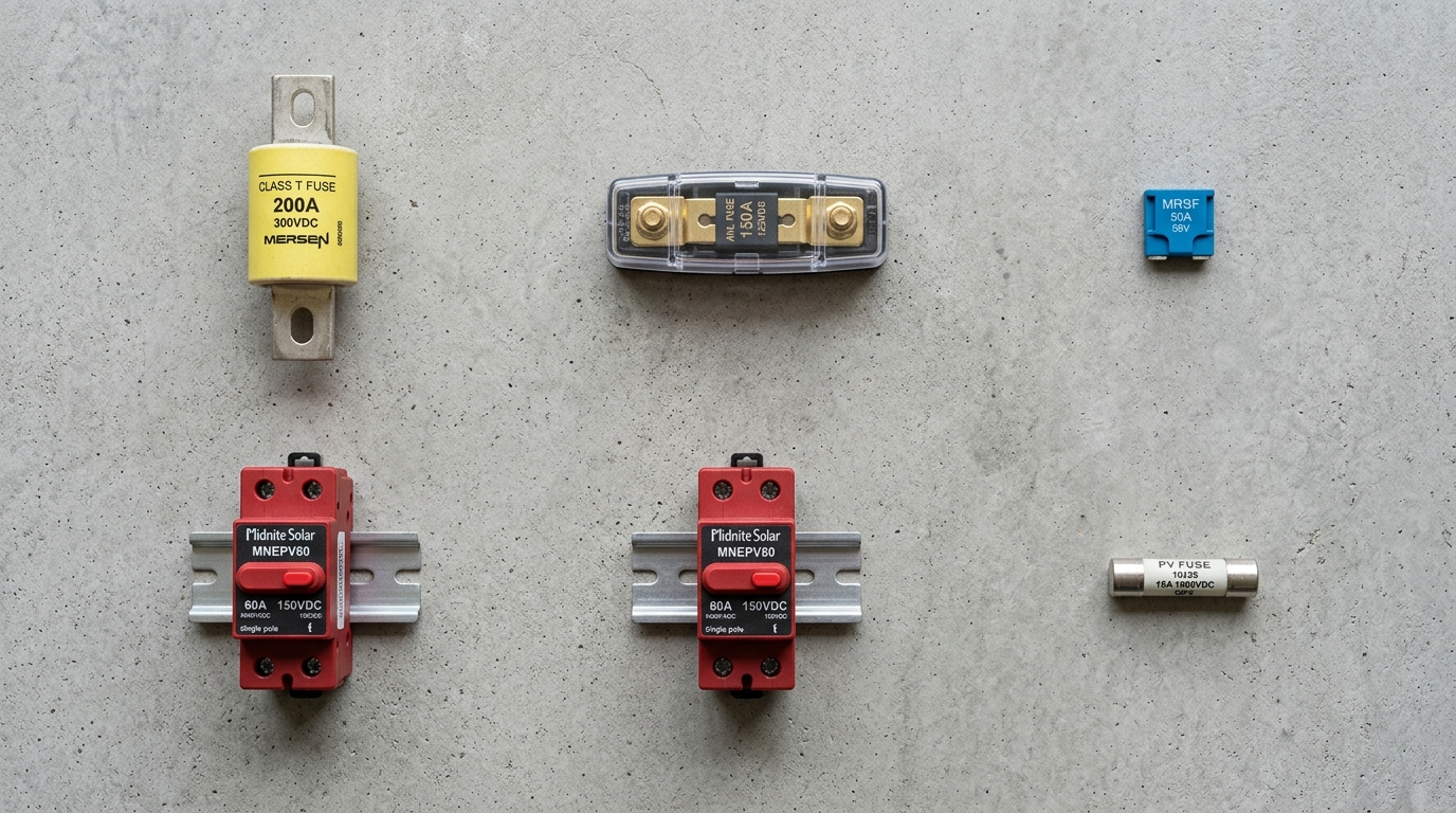
Common Fuse and Breaker Sizes by Application
This is the table I wish I’d had when I was shopping for my own build. Exact sizes depend on your panel Isc and inverter draw, but the columns below cover the vast majority of residential DIY solar scenarios.
| Application | Typical Size | Type | Voltage Rating | Notes |
|---|---|---|---|---|
| PV string fuse (per string) | 10-20A | Midget PV (CC) fuse | 1000-1500VDC | Both conductors on ungrounded arrays |
| Combiner output breaker | 30-60A | DC breaker, UL 489B | 600VDC | Sized at 156% of combined string current |
| Charge controller input | 30-80A | DC breaker or fuse | 150-600VDC | Match controller’s input rating |
| Charge controller to battery | 60-125A | DC breaker or Class T | 125VDC | Between SCC and battery bus |
| MRBF on battery post | 100-300A | MRBF | 58VDC | Protects terminal stub |
| Battery to inverter (main) | 125-400A | Class T | 125VDC | Primary lithium bank protection |
| Small inverter DC input (1-2kW) | 125A | Class T or ANL | 125VDC | 12-24V systems |
| Medium inverter DC input (3-4kW) | 200A | Class T | 125VDC | 48V systems |
| Large inverter DC input (5-8kW) | 250-400A | Class T | 125VDC | 48V systems |
| Inverter AC output (120V, 2kW) | 15-20A | AC breaker | 120VAC | NEC 240 standard |
| Inverter AC output (240V, 6kW) | 30-40A | AC breaker (2-pole) | 240VAC | NEC 240 standard |
| Backfeed breaker to main panel | 30-60A | AC breaker | 240VAC | Subject to 120% rule, 705.12 |
What About NEC 2023 vs 2026?
The overcurrent protection rules in 690.8 and 690.9 didn’t change meaningfully between NEC 2023 and NEC 2026 — the 156% sizing rule and the three-strings-or-more fuse requirement are stable. What did change is the integration with rapid shutdown (690.12) and arc-fault (690.11), which means the inverter and charge controller you choose increasingly do double duty as the overcurrent device, the ground fault detector, and the arc fault detector.
NFPA publishes the NEC on a three-year cycle and NEC 2026 is the current edition. You can check the NFPA 70 standard page for the edition adopted in your state — Rhode Island is on NEC 2023 as of this writing, with NEC 2026 adoption expected in 2026. Your AHJ’s adopted edition is the one that governs your install, regardless of what the latest published edition says.
My Shopping List for a 48V Residential Build
If I were building my current 48V system from scratch today, here’s the overcurrent hardware I’d buy, in approximate order of importance:
- One 200A Class T fuse + insulated holder for main battery protection (~$80)
- Two MRBF holders with 200A fuses for the positive battery terminal(s) (~$60)
- One 63A DC breaker (UL 489B, 150VDC) for the charge controller-to-battery circuit (~$40)
- One 63A DC breaker (600VDC) for the combiner box output (~$50)
- Six 20A PV string fuses (for three or more parallel strings, fuses in both conductors per NEC 690.9 — skip if only 1-2 strings) (~$30)
- One 40A 2-pole AC breaker for the inverter-to-subpanel backfeed (~$25)
- Listed DC disconnect switch if not integrated into the inverter (~$80-150)
Total overcurrent protection budget: roughly $350-450. That’s about 3-4% of a typical 5kW DIY solar build cost, and it’s the 3-4% that keeps the other 96% from burning your house down.
The Mistakes I See Most Often
These are the overcurrent mistakes that come up again and again:
- ANL fuses on lithium banks. Interrupt rating is too low. Replace with Class T.
- AC breakers in DC circuits. Looks the same on the outside, catastrophic on the inside.
- Ignoring polarity on DC breakers. If the breaker says LINE/LOAD, it means it.
- Undersizing by skipping the second 1.25. People remember 690.8(A) and forget 690.8(B). The full factor is 156%, not 125%.
- String fuses in only the positive conductor. On ungrounded (floating) arrays — which is what most modern inverters use — 690.9(C) requires both conductors fused.
- Fuse holder rated for less voltage than the circuit. A 32VDC holder on a 48V system is an arc waiting to happen.
- No MRBF on the battery post. The terminal-to-main-fuse stub is unprotected. Fix it.
None of this is exotic. It’s all standard NEC Article 690 and 240 stuff. But it’s the difference between a system that passes inspection, insures cleanly, and runs safely for decades — and one that becomes a news story.
Putting It All Together
Every conductor in your solar system needs overcurrent protection, and every overcurrent device needs to be sized using the 156% rule, rated for the actual voltage on the circuit (DC or AC), and capable of interrupting the fault current that source can deliver. That’s the whole game.
Before you buy components, sketch a single-line diagram with every fuse and breaker labeled by size, type, and voltage rating. It becomes your shopping list, your permit drawing, and your troubleshooting reference. If you’re still working out the broader code picture, the NEC residential solar reference covers rapid shutdown, grounding, labeling, and the other 690 articles. For the wire side of the equation, the solar wire gauge chart ties fuse sizing and conductor ampacity together.
Overcurrent protection is boring until the moment it isn’t. Do it right the first time.
Frequently Asked Questions
Why do solar circuits use a 156% sizing factor?
NEC 690.8(A) first multiplies Isc by 1.25 to account for irradiance above STC (bright clear days can push current above the nameplate short-circuit rating). NEC 690.8(B) then applies another 1.25 factor because solar circuits operate at maximum current for more than three hours — the NEC definition of a continuous load. Multiplied together, 1.25 × 1.25 = 1.5625, or 156% of Isc.
Why do I need a Class T fuse on a LiFePO4 battery bank?
A 48V LiFePO4 bank can deliver tens of thousands of amps into a dead short for the few milliseconds before the fuse clears. Ordinary ANL or MIDI fuses have interrupt ratings around 2,000-6,000A and can actually fail catastrophically — arcing, spraying molten metal — instead of opening cleanly. Class T fuses carry a 20,000A AIC rating (some models 50,000A) at 125VDC, which is why they're the standard for lithium bank protection.
Can I use an AC breaker on a DC solar circuit?
No. AC breakers rely on the 120-times-per-second zero-crossing of AC current to extinguish the arc when they trip. DC current never crosses zero, so an AC-rated breaker on a DC circuit can sustain an arc inside the breaker housing and start a fire. Always use a breaker specifically listed for DC at or above your system voltage — and observe polarity if the breaker specifies line/load.
Do I need fuses on every PV string?
Per NEC 690.9, you need string fuses once you have three or more strings in parallel. With one or two strings, the module back-feed current from the other string can't exceed the module's series fuse rating, so overcurrent protection isn't required at the combiner. With three or more, a single shorted string can be back-fed by all the others and you need per-string fuses sized at Isc × 1.56.
What size fuse goes between my battery and inverter?
Calculate the inverter's maximum continuous DC input current (watts ÷ battery voltage ÷ efficiency) and size the fuse at roughly 125% of that value, rounded up to a standard size and verified against the cable ampacity. For a 5000W 48V inverter drawing about 110A, a 125A or 150A Class T fuse is typical. Always check the inverter manual — many manufacturers specify the exact fuse size.
Where does the MRBF fuse go on a battery bank?
MRBF (Marine Rated Battery Fuse) holders bolt directly onto the positive battery terminal stud, putting the fuse as close to the energy source as physically possible. This protects the short stub of cable between the battery and the main system fuse or disconnect — a stretch of wire that's otherwise unprotected and sitting inches from a 200Ah lithium cell.
Anthony
Solar homeowner, EV driver, and DIY builder. Using solar to power a large part of my home.
Get build guides in your inbox
Weekly solar builds, product tests, and technical deep-dives.
Subscribe Free