MC4 Connectors and Solar Wiring: Crimping, Tools, and Best Practices
Short answer: Use genuine Staubli/Multi-Contact MC4 connectors or a single reputable brand throughout your entire system — never mix brands. Crimp with a proper MC4 crimping tool (not generic electrician’s crimpers), use PV wire or USE-2 rated for outdoor UV exposure, and pull-test every connection before you button things up. A bad MC4 crimp is the single most common point of failure in residential solar systems, and I’ve replaced more failed crimp connections than any other repair on my own and other people’s systems.
Why MC4 Connections Deserve Serious Attention
MC4 connectors carry hundreds of watts of DC power through a connection the size of your thumb. A properly made MC4 joint has a contact resistance under 0.5 milliohms and is rated for 30+ years of outdoor exposure. A poorly made one develops resistance over time, generates heat, melts the plastic housing, and can start a fire.
I’ve pulled apart MC4 connections on a system only two years old and found the copper contact oxidized green inside the housing. The crimp looked fine from the outside. The resistance across that one connection was 2.3 ohms — enough to dissipate 24 watts of heat at 10A. The plastic was warped and discolored. That connector was heading toward failure.
The fix took ten minutes. Making it right the first time would have taken two. This guide covers how to make it right.
MC4 Connector Types
Standard MC4 Pairs
The basic MC4 connector comes in male and female halves. The male pin inserts into the female socket. They click together with a locking mechanism that requires a disconnect tool (or two flat-blade tools) to separate.
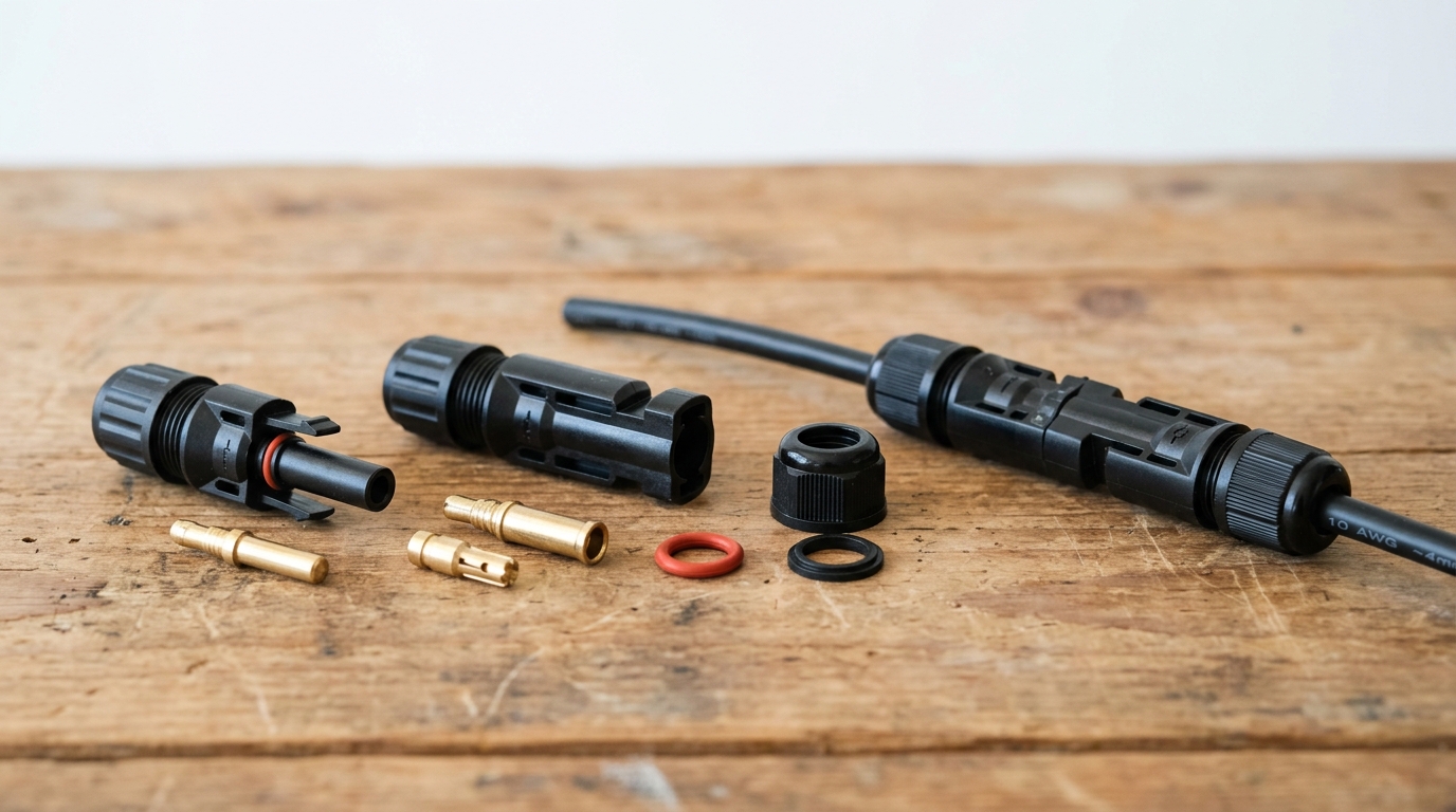
Each connector consists of:
- Metal contact pin/socket — the actual electrical connection, usually tin-plated copper
- Insulating sleeve — fits over the crimped contact
- Housing body — the main waterproof shell
- Cable gland/seal — the threaded back section that compresses a rubber O-ring around the cable
- Locking clip — holds the two halves together
Standard MC4 connectors are rated for 30A at 1000V DC. Most residential panels have Isc under 15A, so a single pair handles any standard panel connection.
Branch Connectors (Y-Connectors)
Branch connectors split one MC4 connection into two (or three, or four). You use these when paralleling strings — two strings combine into one pair of cables going to the combiner box or charge controller.
Common configurations:
- 2-to-1 (Y): Two strings into one output. Most common for residential.
- 3-to-1: Three strings into one output. Less common, usually at the combiner box.
- 4-to-1: Four strings into one. Typically only on commercial systems.
Buy branch connectors that match your main connector brand. A Staubli Y-connector with generic panel connectors is asking for trouble at the junction point.
T-Connectors
T-connectors allow a mid-cable branch without cutting the main run. They’re useful for tapping into a home run cable at intermediate points. I don’t use them often — I prefer running individual string cables to a combiner box — but they have their place on long ground-mount arrays where running separate cables from each string back to the equipment pad would waste a lot of copper.
Inline Fuse Holders
MC4-style inline fuse holders accept a standard 10×38mm PV fuse and install in-line with your MC4 cabling. They’re an alternative to a combiner box for small systems with 2-3 strings. Each string gets its own fused connector on the positive leg.
I used inline fuse holders on my shed system (2 strings, 2S each) and they’ve been fine for two years. For anything larger, a proper combiner box is cleaner and easier to service.
Tools You Need
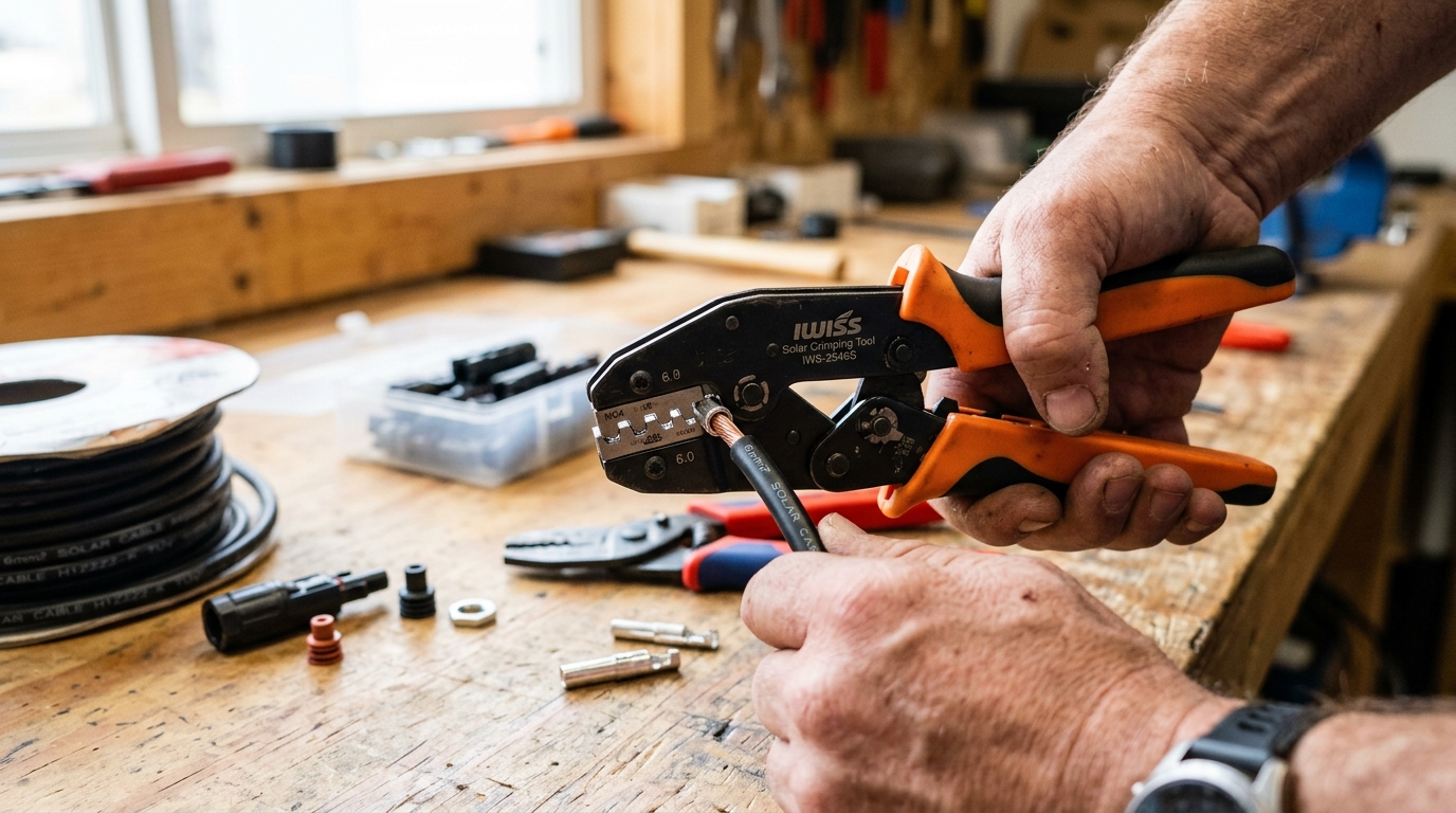
MC4 Crimping Tool
This is the one tool you cannot substitute. A proper MC4 crimping tool has dies shaped specifically for the MC4 contact pin geometry — they create a hexagonal crimp that compresses the contact barrel evenly around the wire strands.
What to buy: The genuine Staubli PV-CZM-22100 crimping tool runs about $300. If that’s outside your budget (it was outside mine), the IWISS LY-2546B (~$35) is the most widely recommended affordable alternative in the DIY solar community. I’ve made over 200 crimps with mine and haven’t had a failure.
What NOT to use:
- Generic ratcheting crimpers (wrong die shape — creates an oval crimp instead of hexagonal)
- Pliers (terrible contact, will fail)
- Hammer and anvil (yes, I’ve seen someone try this)
The hexagonal crimp is what gives the MC4 connection its low resistance and mechanical strength. An oval crimp from generic tools may look similar, but the contact area is smaller and the wire strands aren’t compressed uniformly. Under thermal cycling (hot days, cold nights, for years), an oval crimp loosens faster.
Wire Stripper
You need a stripper that handles 10-12 AWG wire cleanly without nicking strands. A nicked strand reduces the conductor cross-section at exactly the point where it enters the crimp — the worst possible place for a weak spot.
I use an automatic wire stripper (the Klein 11063W, about $30) that adjusts to the wire diameter. Set it, squeeze it, done. If you’re using a manual stripper, practice on scrap wire first and inspect every strip under good light.
Strip length: 8-9mm for standard MC4 contacts. Too short and the wire doesn’t reach the full barrel depth. Too long and bare copper extends past the barrel into the insulation area, which can contact the housing or compromise the seal.
Multimeter
A basic digital multimeter with DC voltage and resistance (continuity) modes. After crimping, you’ll check:
- Continuity through each connector (should beep immediately — any hesitation indicates a bad crimp)
- Resistance across a mated pair (under 1 milliohm for a good connection — most meters can’t read this low, so you’re checking for “not obviously bad” rather than precise values)
- Voltage at the connector output with panels connected (verifying polarity and expected Voc)
You don’t need an expensive meter for this. A $25 auto-ranging multimeter from any hardware store works fine.
MC4 Disconnect Tool
A flat plastic tool that slides into the locking mechanism on each side of a mated MC4 pair, allowing you to separate them. You can buy a pair for $5, or use two small flat-blade screwdrivers. I keep a disconnect tool in my pocket whenever I’m working on the array.
Pulling MC4 connectors apart without the tool damages the locking clips and compromises the weather seal. Using pliers to yank them apart might look harmless, but those connectors will leak water within a year.
Step-by-Step Crimping Technique
Preparation
-
Cut your wire to length. Add 6 inches of slack beyond what you think you need. You can always tuck slack behind a panel; you can’t stretch a wire that’s too short.
-
Slide the cable gland components onto the wire FIRST. This is the step everyone forgets on their first connector. The threading nut and rubber seal must be on the wire before you crimp the contact. If you crimp first, you have to cut the contact off and start over. I’ve done this three times before I made it an automatic habit.
The order from the cut end of the wire inward: nothing yet (this is where the contact goes), then the insulation sleeve, then the rubber O-ring seal, then the compression nut, then the housing body — or follow the specific assembly order for your brand. Some brands vary slightly. Lay out a disassembled connector and thread each piece onto the wire in reverse assembly order.
- Strip the wire. Remove 8-9mm of insulation. Inspect the stripped end:
- All strands intact? (If you nicked strands, cut back and re-strip)
- Clean copper? (If it’s oxidized or tarnished, cut back to fresh copper)
- Straight strands? (Twist them lightly to keep them bundled)
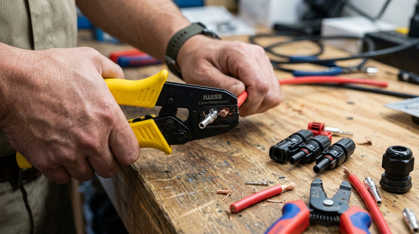
Crimping
-
Insert the wire into the contact barrel. The stripped copper should extend to the inspection window (a small hole in the barrel of the contact). You should see copper through the window. If you see insulation, the wire isn’t in far enough. If you see nothing, the wire went too far and you should pull it back slightly.
-
Place the contact in the crimping tool. The barrel sits in the die, positioned so the crimp compresses the barrel where the wire is. For the IWISS LY-2546B, use the 2.5mm² die for 14 AWG wire and the 4.0mm² die for 12 AWG wire. Match the die to your wire gauge — using the wrong die creates a loose or over-compressed crimp.
-
Squeeze the crimper fully. Ratcheting crimpers won’t release until they’ve completed the full stroke. This is a feature, not a flaw — it ensures consistent crimp pressure. Squeeze until the ratchet releases.
-
Inspect the crimp. Look for:
- Hexagonal shape (not oval, not round)
- Wire visible in the inspection window
- No wire strands poking out the sides
- Insulation butted up against the end of the barrel (no bare copper between insulation and barrel)
Assembly
-
Slide the insulation sleeve over the crimp. It should snap or slide firmly into place over the barrel.
-
Insert the contact assembly into the housing body. Push until it clicks — the internal latch catches the contact and prevents it from pulling out. Pull back on the wire firmly to confirm it’s seated. If it slides out, the latch didn’t engage; reinsert and listen for the click.
-
Thread the cable gland. Slide the rubber seal into position and thread the compression nut onto the housing. Hand-tight is sufficient — the seal should compress around the cable jacket without deforming it.
Verification
-
Pull test. Grab the wire in one hand and the connector housing in the other. Pull hard — 20-30 pounds of force. A properly crimped and seated contact will not move. If it pulls out, the crimp failed or the internal latch didn’t engage.
-
Continuity test. Touch your multimeter probes to the metal contact face and the wire at the other end. You should get a zero-resistance beep. Any hesitation or fluctuating reading means the crimp has high resistance.
-
Repeat for the other end. Each cable gets a male on one end and a female on the other (for extension cables) or matches the panel’s existing connector gender (for adapter cables).
Wire Selection for Outdoor Solar Runs
Not all wire is rated for outdoor solar use. The wire between your panels and your charge controller or combiner box is exposed to UV radiation, temperature extremes, moisture, and physical stress. Using indoor-rated wire outdoors is a code violation and a fire hazard — the insulation degrades within 2-3 years.
PV Wire (Photovoltaic Wire)
PV wire is purpose-built for solar installations. It’s rated for:
- 90°C wet or dry
- 600V or 1000V (check the specific product)
- UV resistant
- Sunlight resistant (marked “SUNLIGHT RESISTANT” on the jacket)
- Direct burial (most types)
- Single-conductor, flexible stranding
PV wire is my default choice for any exposed run from panels to the combiner box or equipment location. It’s available in 10 AWG and 12 AWG pre-made with MC4 connectors attached, which saves crimping time for standard panel-to-panel connections.
USE-2 (Underground Service Entrance)
USE-2 wire is rated for:
- 90°C wet
- 600V
- UV resistant (when marked “SUNLIGHT RESISTANT”)
- Direct burial
- Underground conduit
USE-2 is interchangeable with PV wire for most residential solar applications. It’s sometimes easier to find locally at electrical supply houses. Make sure it’s marked “SUNLIGHT RESISTANT” — not all USE-2 has this rating.
THWN-2
THWN-2 is the standard building wire rated for:
- 90°C wet or dry
- 600V
- Conduit or raceway installation
THWN-2 is not UV resistant by default. It’s fine inside conduit but should not be used for exposed outdoor runs. If your entire outdoor cable path is in conduit, THWN-2 works and is often cheaper than PV wire.
For sizing any of these wire types, the solar wire gauge chart gives you quick lookup tables, and the Wire Gauge Calculator handles exact calculations for your specific run distance and current. NEC ampacity and conduit derating are covered in the NEC code requirements guide.
What About THHN?
THHN is dry-rated only. Never use it for outdoor solar wiring, even in conduit — conduit on a roof accumulates condensation. Dual-rated THHN/THWN-2 wire is common and works fine; just verify the “THWN-2” marking is present.
Why You Should Never Mix MC4 Brands
MC4 is a connector standard originally designed by Multi-Contact (now Staubli). The name “MC4” is technically a trademark, but it’s become a generic term for the connector form factor. Dozens of manufacturers make “MC4-compatible” connectors.
The problem: they’re not all actually compatible.
The external locking mechanism dimensions are similar enough that a male connector from Brand A will physically click into a female connector from Brand B. It feels like a connection. But the internal contact pin and socket dimensions can differ by tenths of a millimeter — enough to reduce contact area, increase resistance, and cause overheating over time.
I learned this the hard way. My first panel array used panels from two different manufacturers. Both came with MC4 connectors pre-wired, and they clicked together just fine. After 14 months, I noticed one connection was warm to the touch on a sunny day — a connector running at panel temperature should never be warm, because the power flowing through it should generate negligible heat at proper contact resistance.
I pulled that connection apart and the female socket contact had a visible heat mark where the contact area had been reduced by the slight pin diameter mismatch. The resistance across that one connection measured 0.8 ohms — it should have been essentially zero.
The rule: Pick one brand and use it everywhere. If your panels come with Brand X connectors and your extension cables are Brand Y, either replace the panel connectors or the extension cables so everything matches. Staubli (the original) is the gold standard, but Amphenol H4, Phoenix Contact SUNCLIX, and a few others are quality options.
For extension cables and branch connectors, buy from the same brand as your panel connectors, or replace everything with one brand.
Waterproofing and Strain Relief
MC4 connectors are IP67-rated when properly assembled — meaning they can be submerged in 1 meter of water for 30 minutes without leaking. But that rating assumes:
- The cable gland is properly tightened and the O-ring is compressed around the wire jacket
- The wire diameter matches the gland range — too thin and the O-ring can’t seal; too thick and the gland won’t compress fully
- The connectors are mated and locked — an unmated connector is NOT waterproof
Things that compromise the seal:
- Over-tightening the cable gland (deforms the O-ring permanently)
- Using wire that’s too small for the gland (10 AWG PV wire in a gland designed for 8 AWG — the O-ring doesn’t compress)
- Damaged or missing O-rings
- Cracked housings from UV degradation (cheap knockoff connectors are notorious for this)
- Connectors hanging vertically with the opening facing up (water pools in the locking mechanism)
Best practice: Orient connections horizontally or with the opening facing down. On my roof, I use drip loops — a U-shaped bend in the cable below the connector so water runs down the cable, around the loop, and drips off the bottom instead of running into the connector.
For strain relief, I secure cables every 18-24 inches with UV-rated cable clips. PV wire is heavy, and a long unsupported run puts stress on the MC4 connection at each end. Wind vibration accelerates this — a cable flapping in the wind fatigues the crimp over thousands of cycles.
Junction Box Wiring
The junction box on the back of each solar panel is where the cell strings connect to the output cables. Most modern panels have pre-wired MC4 pigtails — you never need to open the junction box in normal installation.
When you do need to access it:
- Replacing a damaged pigtail (connector housing cracked, cable cut)
- Extending cables (panel pigtails are typically 3-4 feet — sometimes not long enough)
- Troubleshooting (checking bypass diode function, testing individual cell strings)
If you open a junction box:
- Disconnect the panel from all circuits first. Cover the panel face with an opaque tarp — even disconnected, a panel produces voltage in sunlight.
- Note the existing wiring before touching anything. Take a photo.
- Use proper solar-rated wire for any replacements — the same PV wire or USE-2 discussed above.
- Reseal the junction box with the original gasket and sealant. If the gasket is damaged, apply a bead of silicone sealant rated for high temperature (the junction box can reach 85°C+).
- Test before reassembling. Measure Voc at the MC4 connectors to confirm correct wiring and polarity.
I’ve only had to open a junction box twice — once for a rodent-damaged cable (squirrels chewed through the PV wire at the box entry) and once to test bypass diodes on a panel that was showing abnormally low output. For diagnosing low panel output, see the troubleshooting guide.
Common Mistakes and How to Avoid Them
1. Forgetting to pre-thread the gland components. I covered this above, but it’s worth repeating — it’s the single most common mistake I see. You cannot thread the nut over a crimped contact. Stop. Check. Then crimp.
2. Using the wrong crimp die size. 12 AWG wire in a 10 AWG die results in a loose crimp that passes the initial pull test but develops resistance over thermal cycling. Match the die to the wire gauge exactly.
3. Stripping too much or too little insulation. Too much exposes copper that can contact the housing. Too little means the wire doesn’t fully engage the contact barrel. Use a ruler or the contact itself as a gauge — hold the stripped end against the barrel and verify the copper reaches the inspection window.
4. Not pull-testing. Every single crimp gets a pull test. Every one. I’ve had crimps that looked perfect fail the pull test because the internal latch didn’t click. The pull test takes two seconds and catches problems before they’re 20 feet up on your roof.
5. Leaving unmated connectors exposed. Every unused MC4 connector needs a weatherproof cap. Exposed contacts corrode, and an open female connector is a shock hazard — panel voltage is present any time the sun is shining.
6. Running MC4 connections under panels where you can’t inspect them. Route cables to the edges of the array where you can visually inspect connections from the ground or roof edge. A failing connector hidden under the center of a panel array is a fire risk you can’t see.
7. Using indoor wire outdoors. THHN in exposed outdoor runs degrades in UV within 2-3 years. The insulation cracks, moisture enters, and the copper corrodes inside the connector. Use PV wire or USE-2 for any outdoor run.
Tools Summary and Cost
| Tool | Purpose | Cost | Necessity |
|---|---|---|---|
| MC4 crimping tool (IWISS LY-2546B) | Crimping contacts | ~$35 | Required |
| Wire stripper (auto-adjusting) | Stripping PV wire | ~$20-30 | Required |
| Digital multimeter | Testing connections | ~$25 | Required |
| MC4 disconnect tool pair | Separating connections | ~$5 | Required |
| Cable cutters | Cutting PV wire | ~$15 | Required |
| UV-rated cable ties/clips | Securing cable runs | ~$10 | Required |
| MC4 weatherproof caps | Protecting unused connectors | ~$8 | Required |
| Total | ~$120-130 |
You’ll use these tools on every solar project going forward. The crimping tool alone pays for itself the first time you need to make a custom-length cable instead of buying a pre-made one at 3x the price.
Putting It Together
Good MC4 connections are boring. They crimp, they click, they sit on your roof for decades without needing attention. Bad MC4 connections give you intermittent power drops, unexplained low production, and eventually a service call or a fire.
Take the time to practice crimping on scrap wire before you do your actual installation cables. Make three or four practice crimps, pull-test them to destruction, and inspect the contact area. You’ll quickly develop the feel for a proper crimp versus a marginal one.
For the full picture on wiring your system — panel configuration, wire sizing, and charge controller selection — start with the panel wiring guide, size your cables with the Wire Gauge Calculator, and check the solar wire gauge chart for quick reference. If you’re building your first system from scratch, the getting started guide puts it all in order.
Frequently Asked Questions
Can I mix different brands of MC4 connectors?
No. While different brands may physically click together, internal contact pin and socket dimensions can differ by tenths of a millimeter. This reduces contact area, increases resistance, and causes overheating over time. Pick one brand and use it throughout your entire system.
What tool do I need to crimp MC4 connectors?
Use a proper MC4 crimping tool with hexagonal dies — not generic electrician crimpers. The IWISS LY-2546B (about $35) is the most widely recommended affordable option in the DIY solar community. Generic tools create oval crimps that fail under thermal cycling.
What wire should I use for outdoor solar panel connections?
Use PV wire or USE-2 wire rated for outdoor UV exposure. Both are rated for 90 degrees C and are sunlight resistant. THWN-2 is acceptable inside conduit but is not UV resistant for exposed runs. Never use THHN for outdoor solar wiring.
How do I know if an MC4 crimp is good?
A proper crimp should have a hexagonal shape (not oval), show copper in the inspection window, have no wire strands poking out the sides, and pass a 20-30 pound pull test without moving. Always test continuity with a multimeter after crimping.
Why do MC4 connectors fail?
The most common failures are poor crimps (wrong tool or technique), mixing connector brands, moisture intrusion from improper cable gland sealing, and UV degradation of cheap knockoff housings. A bad crimp develops resistance over time, generating heat that melts the housing.
Anthony
Solar homeowner, EV driver, and DIY builder. Using solar to power a large part of my home.
Get build guides in your inbox
Weekly solar builds, product tests, and technical deep-dives.
Subscribe Free